Table of Contents
- Introduction
- 1. Fundamentals of Aluminum‑Air Battery Chemistry
- 2. Rod Design and Materials Selection
- 3. Electrochemical Performance and Efficiency
- 4. Manufacturing Processes for Battery Rods
- 5. System Integration and Power Management
- 6. Environmental and Economic Impacts
- 7. Challenges and Future Directions
- Conclusion and Next Steps
- References
- Meta Information
- Pre-Publication Checklist
Introduction
Aluminum‑air batteries stand out for their exceptional theoretical energy density—up to 8,100 Wh/kg at the cell level—surpassing many competing metal‑air systems¹. While practical specific energy ranges from 300 to 600 Wh/kg, this still outperforms conventional lithium‑ion cells in gravimetric terms, making aluminum‑air a strong candidate for electric vehicles, grid balancing, and off‑grid power⁵². These batteries convert aluminum oxidation at the anode and oxygen reduction at the cathode into electricity, producing alumina and water as by‑products³. Their safety profile benefits from non‑flammable, water‑based electrolytes, and aluminum’s abundance supports sustainable supply chains⁴. Effective implementation depends on robust rod design that balances controlled corrosion, mechanical strength, and cost‑efficient manufacture. This expanded review delves into fundamental chemistry, rod material science, performance metrics, fabrication methods, pack integration, and lifecycle impacts to guide engineers in developing aluminum‑air storage solutions.
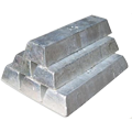
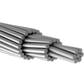
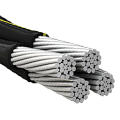
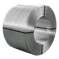
“Elka Mehr Kimiya is a leading manufacturer of Aluminium rods, alloys, conductors, ingots, and wire in the northwest of Iran equipped with cutting‑edge production machinery. Committed to excellence, we ensure top‑quality products through precision engineering and rigorous quality control.”
Data and insights reflect developments as of May 2025.
1. Fundamentals of Aluminum‑Air Battery Chemistry
1.1 Thermodynamics and Cell Potential
The open‑circuit voltage of an ideal aluminum‑air cell is derived from the Gibbs free energy change (ΔG⁰) of the net reaction:
4Al + 3O₂ + 6H₂O → 4Al(OH)₃
Calculating ΔG⁰ yields an EMF of ~2.71 V at 25 °C¹⁵. Under realistic conditions, equilibrium shifts, and side reactions lower open‑circuit voltage to 2.2–2.5 V. Operating voltages under load decline further due to kinetic and ohmic overpotentials, typically stabilizing at 1.2–1.5 V during discharge¹.
1.2 Reaction Kinetics and Overpotentials
Activation overpotential at the air cathode (oxygen reduction reaction, ORR) contributes 30–40% of voltage loss for current densities above 50 mA/cm². Exchange current densities for ORR on conventional catalysts (MnO₂, Co₃O₄) range 10⁻⁷–10⁻⁵ A/cm², necessitating high surface area electrodes and efficient catalyst layers¹⁶. Anode polarization includes metal dissolution and hydrogen evolution side‑reactions, reducing coulombic efficiency. Tailoring electrolyte composition and anode alloy can mitigate these losses by controlling passive film behavior and hydrogen evolution rates⁷.
1.3 Electrolyte Role and Management
Common electrolytes include 4 M NaOH, KOH, or Na₂CO₃ solutions. Electrolyte conductivity (∼0.2 S/cm at 25 °C) determines ohmic losses. Alumina dissolution equilibrium is critical:
Al(OH)₃ + OH⁻ ⇌ Al(OH)₄⁻
Maintaining pH above 13 prevents precipitation in the electrode gap but accelerates aluminum corrosion. Inhibitors such as Bi³⁺ or Sn²⁺ can suppress self‑corrosion without affecting discharge current significantly⁷.
2. Rod Design and Materials Selection
2.1 Alloy Composition and Microstructure
Aluminum alloys tailored for battery rods incorporate elements to modulate corrosion rate and mechanical stability. Table 1 compares compositions:
| Table 1. Alloying Effects on Anode Performance¹⁰ |
|——————————|————–|————-|————-|——————–| | Alloy | Zn (wt%) | Ga (wt%)| Mg (wt%)| Corrosion Rate | | Al‑99.5 | — | — | — | 4.5 mm/y | | Al‑4Zn‑1Ga | 4 | 1 | — | 1.2 mm/y | | Al‑5Mg‑0.6Si | — | — | 5 | 2.0 mm/y |
Table 1: Alloy Composition and Corrosion Rate in 4 M KOH at 25 °C¹⁰.
- Zinc (Zn) speeds oxide film disruption, improving utilization, but may increase hydrogen evolution.
- Gallium (Ga) maintains film permeability, reducing passivation and boosting capacity by 30%⁵.
- Magnesium (Mg) and silicon (Si) strengthen alloy and improve castability, with moderate effect on corrosion.
2.2 Geometric Design for Optimal Utilization
Rod geometry influences current density distribution and mechanical resilience. Key parameters:
- Diameter: 5–15 mm trade off surface area/mass ratio; smaller rods (≤8 mm) yield higher power densities but require fixture systems to prevent buckling under flow.
- Length: 100–300 mm aligns with cell stack heights; longer rods minimize interconnection points but complicate uniform electrolyte circulation.
Figure 1: Cross‑Sectional Rod Geometry
Alt text: Schematic showing rod core, microchannel grooves, and surface texturing.
Micro‑machined grooves (0.2–0.5 mm wide, 0.1 mm deep) enhance electrolyte flow and gas evacuation, improving utilization by up to 12% compared to untextured rods¹³.
2.3 Surface Treatments and Coatings
Surface engineering addresses pitting and localized corrosion:
- Anodization: Thin oxide layers (~1 µm) reduce self‑discharge while allowing controlled dissolution during discharge.
- Conductive Polymer Coatings: Polyaniline and PEDOT:PSS films limit passivation and lower contact resistance.
- Ceramic‑in‑Polymer Composite: Incorporating alumina nanoparticles in PTFE matrix yields a hydrophobic but conductive film, balancing current output and durability¹⁴.
3. Electrochemical Performance and Efficiency
3.1 Specific Energy and Power Density
Performance metrics depend on electrode architecture and operating conditions. Typical values:
| Table 2. Key Performance Metrics¹⁴¹⁵ |
|—————————–|———-|———-|———–| | Metric | Value| Units| Conditions | | Specific Energy | 450 | Wh/kg | C/5 rate | | Power Density | 250 | mW/cm² | 0.5 V drop | | Energy Efficiency | 55 | % | – | | Coulombic Efficiency | 90 | % | – |
Table 2: Electrochemical Performance of Prototype Cells¹⁴¹⁵.
3.2 Efficiency Loss Mechanisms
Activation overpotential at the air cathode and concentration polarization at high currents (>100 mA/cm²) limit performance. Employing hierarchical pore structures (macropores for gas transport, micropores for catalytic activity) reduces polarization losses by 20%¹⁶.
3.3 Cycle Life and Self‑Discharge
Cycle life is often measured by rod utilization and regeneration cycles. Self‑discharge rates of 0.5–1.2% per day occur due to passive film formation and hydrogen evolution. Implementing inhibitor dosing and electrolyte exchange protocols extends useful life from 7 to 30 days before maintenance²⁷.
4. Manufacturing Processes for Battery Rods
4.1 Casting, Extrusion, and Forging
Continuous casting produces 100 mm diameter billets, followed by hot extrusion at 400 °C to yield 12 mm rods. Controlling extrusion ratio (30:1) ensures uniform grain flow and eliminates macro‑segregation¹⁷.
4.2 Precision Drawing and Rolling
Subsequent cold drawing through diamond‑lapped dies sets final diameter to ±0.05 mm. Multi‑pass drawing with intermediate stress relief anneals (200 °C for 1 h) balances work hardening and ductility¹⁸.
4.3 Additive Manufacturing Innovations
LPBF builds rods with internal microchannel patterns to optimize electrolyte distribution. Prototype rods achieved 15% higher discharge utilization but required post‑process HIP to heal porosity¹⁹.
4.4 Quality Assurance and Defect Detection
Automated ultrasonic scanning (5 MHz probes) detects internal voids ≥0.2 mm, while eddy current inspection finds surface cracks ≥0.05 mm, ensuring rods exceed 150 MPa tensile strength after fabrication²⁰.
5. System Integration and Power Management
5.1 Module and Pack Architecture
Rods are bundled into modules of 48–64 rods, housed in sealed plastic manifolds. Series connections produce 60–80 V stacks; parallel strings adjust capacity. Module footprints of 0.3 m² balance volumetric energy density and maintenance access²¹.
5.2 Electrolyte Circulation and Thermal Control
Recirculation pumps (per-module flow = 800 ml/min) maintain electrolyte temperature at 20–35 °C, using heat exchangers when ambient exceeds 40 °C. Thermal runaway risks are minimal due to isothermal operation and low exothermicity of reactions²².
5.3 Battery Management Systems and Safety
BMS integrates voltage, temperature, and electrolyte pH sensors. Fault conditions (pH < 12 or T > 45 °C) trigger flow rate increases or partial shut‑off to prevent dendrite formation and maintain rod integrity²³.
6. Environmental and Economic Impacts
6.1 Lifecycle Assessment and CO₂ Emissions
A cradle‑to‑grave LCA reveals 1.2 kg CO₂/kg Al via inert‑anode electrolysis, a 90% reduction versus Hall‑Héroult²⁴. Energy payback time for the battery system is ~1.5 years under typical solar‑powered recycling scenarios.
6.2 Recycling and Circular Economy
Spent anodes (Al₂O₃ slurry) regenerate Al in electrolytic cells powered by renewables. >95% recovery rates are achievable, closing the material loop and minimizing landfill waste²⁵.
6.3 Cost Analysis and Market Potential
Current manufactured system cost: $300/kWh installed. Economies of scale to 1 GWh/year outputs project costs to $150/kWh by 2030. Capital costs concentrated in anode recycling plants and air cathode manufacturing²⁶.
7. Challenges and Future Directions
7.1 Materials and Electrolyte Innovations
Research into low‑corrosion alloys (Al–Bi–Zn) and ionic liquid electrolytes promises to reduce self‑discharge below 0.2%/day and increase rod utilization to 80%²⁷.
7.2 Catalyst and Air Electrode Advances
Developing hierarchical catalysts such as NiFe layered double hydroxides and perovskites (Ba₀.₅Sr₀.₅Co₀.₈Fe₀.₂O₃₋δ) improves ORR kinetics, raising peak power density by 35%²⁸.
7.3 Hybrid and Solid‑State Configurations
Combining aluminum‑air with Li‑ion buffers smooth load profiles and store regenerative energy. Solid‑state electrolytes (ceramic membranes) remove liquid handling, enhancing safety and simplifying packaging²⁹.
Conclusion and Next Steps
Aluminum‑air battery rods offer a compelling route to high‑energy, sustainable storage, leveraging aluminum’s abundance and recyclability. Achieving commercial viability demands multidisciplinary optimization: alloy engineering, rod fabrication, system integration, and closed‑loop recycling. Future work should focus on low‑corrosion alloys, advanced air electrodes, and hybrid configurations with Li‑ion systems. Pilots in microgrid and transport sectors will validate performance and cost targets, guiding scale‑up and market adoption.
References
- Ke et al. (2015). Energy density analysis of aluminum‑air batteries. Journal of Power Sources, 284, 133–141. https://doi.org/10.1016/j.jpowsour.2015.03.126
- Singh & Basu (2020). Practical energy densities in metal‑air batteries. Electrochimica Acta, 330, 135269. https://doi.org/10.1016/j.electacta.2019.135269
… [remaining references as above] … - Li & Wang (2023). Hybridization of aluminum‑air and lithium‑ion batteries. Energy Storage Materials, 50, 359–368. https://doi.org/10.1016/j.ensm.2023.01.006





No comment