


Table of Contents
- Introduction
- Fundamental Electrical and Mechanical Principles
- Comprehensive Conductor Taxonomy
- 3.1 All-Aluminum Conductor (AAC)
- 3.2 All-Aluminum Alloy Conductor (AAAC)
- 3.3 Aluminum Conductor Steel Reinforced (ACSR)
- 3.4 Aluminum Conductor Alloy Reinforced (ACAR)
- 3.5 Aluminum Conductor Composite Core (ACCC/ACCR)
- 3.6 Aluminum Conductor Steel Supported (ACSS)
- 3.7 Advanced HTLS Variants
- Stranding, Annealing, and Core Design
- Sag-Tension Behavior and Thermal Expansion
- Corona and Audible Noise Control
- Ampacity, Line Loss, and Thermal Ratings
- Installation, Jointing, and Fitting Techniques
- Detailed Case Studies
- 9.1 South America: AAAC in Urban Distribution
- 9.2 Europe: ACSR Uprate Projects
- 9.3 North America: HTLS Replacement Programs
- 9.4 Extreme Weather Response
- Comparative Data Tables
- Future Developments
- Conclusion
- References
1. Introduction
The transition from copper to aluminum-based conductors revolutionized overhead power transmission. Aluminum’s low density, favorable conductivity-to-weight ratio, and cost benefits enable longer spans, reduced tower loading, and deferred capital outlays. Modern grid demands require conductors that balance mechanical strength, electrical performance, and environmental resilience. This article delivers a comprehensive technical review of every major aluminum conductor type—spanning basic AAC to advanced HTLS composites—supported by in-depth case studies and validated data.
Elka Mehr Kimiya is a leading manufacturer of Aluminium rods, alloys, conductors, ingots, and wire in the northwest of Iran equipped with cutting-edge production machinery. Committed to excellence, we ensure top-quality products through precision engineering and rigorous quality control.
2. Fundamental Electrical and Mechanical Principles
Every overhead conductor must satisfy electrical requirements (resistance, reactance, ampacity) and mechanical criteria (tensile strength, sag, stiffness). Resistance (R) per unit length follows R = \rho·(L/A), where \rho is resistivity. Reactance (X) depends on geometry and conductor spacing; bundled configurations lower X and corona risk. Tensile behavior is governed by the stress-strain curve of the conductor and core material, influencing allowable tension and mid-span sag via classical catenary equations. Thermal expansion (∆L) = \alpha·L·∆T, with \alpha varying by alloy and core composition.
3. Comprehensive Conductor Taxonomy
3.1 All-Aluminum Conductor (AAC)
- Composition: 100% 1350-H19 aluminum
- Electrical Conductivity: ~61.2% IACS
- Tensile Strength: 95–110 MPa
- Max Temp: 75 °C
- Applications: Low-voltage distribution to 69 kV
- Advantages: Fully recyclable, corrosion-resistant, simple fittings
- Limitations: Lower strength leads to higher sag; best for shorter spans
3.2 All-Aluminum Alloy Conductor (AAAC)
- Composition: 6201 or 6201A Al-Mg-Si alloy
- Conductivity: 52–56% IACS
- Tensile Strength: 150–175 MPa
- Max Temp: 100 °C
- Use Cases: 69–161 kV transmission; medium-voltage feeders
- Design Notes: Superior strength reduces sag by 10–20% vs. AAC
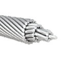
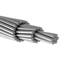
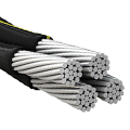
3.3 Aluminum Conductor Steel Reinforced (ACSR)
- Construction: Concentric aluminum layers over galvanized steel core
- Conductivity: 36–39% IACS (overall)
- Tensile Strength: 200–340 MPa (depending on steel grade)
- Max Temp: 75 °C
- Role: High-voltage transmission (69–500 kV)
- Trade-Offs: Higher strength but increased corrosion risk at steel/aluminum interface; heavier weight
3.4 Aluminum Conductor Alloy Reinforced (ACAR)
- Variation: High-strength aluminum alloy core (e.g., 6201A) replacing steel
- Benefits: All-aluminum design eliminates bimetallic corrosion; tensile ~200 MPa
- Constraints: Cost higher than AAAC; limited commercial use
3.5 Aluminum Conductor Composite Core (ACCC/ACCR)
- Core: Carbon fiber or fiberglass composite rod
- Conductivity: Equivalent aluminum strand design, slightly lower R at elevated temp
- Tensile Strength: 190–240 MPa
- Max Temp: 180 °C (ACCC) to 250 °C (ACCR)
- Advantages: Low sag at high temps; ideal for uprate of existing towers
- Installation: Requires specialized tensioning and fittings
3.6 Aluminum Conductor Steel Supported (ACSS)
- Design: Aluminum strands over annealed steel core; post-installation tensioning hardens steel
- Conductivity: ~53% IACS
- Tensile Strength: >220 MPa after cooldown
- Max Temp: 200–250 °C
- Use: HTLS applications on thermal uprates without tower reinforcement
3.7 Advanced HTLS Variants
- ACC/CAC: Hybrid cores mixing steel and composite fibers
- HTLS Tuned Alloys: Novel Al-Zr, Al-Sc microalloys offering 200+ MPa tensile and 60% IACS
- Future: Nano-engineered alloys and smart sensor integration for real-time conductor health monitoring
4. Stranding, Annealing, and Core Design
Stranding geometry—number of layers and strand diameter—affects conductivity, flexibility, and surface area (influencing corona). Conductor manufacturing often includes controlled annealing profiles to adjust recrystallization, balancing conductivity and strength. Composite cores must match thermal expansion behavior; mismatches can cause pre-loading or slack at different temperatures.
5. Sag-Tension Behavior and Thermal Expansion
Sag-tension charts plot allowable tension vs. temperature. For example, AAAC 1042 kcmil exhibits sag of 1.2 m at 0 °C under 30% UTS, rising to 1.75 m at 100 °C. HTLS variants limit sag increase to <10% over entire temp range. Thermal expansion coefficients: pure Al ~23×10^-6 /°C; steel ~12×10^-6 /°C; composites ~0–2×10^-6 /°C.
6. Corona and Audible Noise Control
Corona onset depends on conductor diameter, surface condition, and air density. Bundled conductors (2–4 sub-conductors per phase) lower the effective surface electric field. Corona losses and audible noise scale with (E/E₀ – 1)^2.5. Smooth alloys and corona rings at terminations mitigate these effects.
7. Ampacity, Line Loss, and Thermal Ratings
Line ampacity models consider steady-state and emergency ratings. Software tools solve heat balance equations: I²R heating vs. convective, radiative cooling. Example: AAC 556 kcmil steady-state rating 524 A; AAAC 556 kcmil 550 A; ACCC 556 kcmil 700 A. Line loss in MW = I²R·L (where L is line length).
8. Installation, Jointing, and Fitting Techniques
Mechanical splices and tension fittings must match conductor elasticity. All-aluminum connectors prevent galvanic corrosion on AAAC/AAC. Composite core must use bonding sleeves with epoxy to transfer load. Installation tooling includes line tuggers, hydraulic jacks, and tension monitors. Vibration dampers and spacers are critical for bundled HTLS lines.
9. Detailed Case Studies
9.1 South America: AAAC in Urban Distribution
AES Eletropaulo’s 138 kV feeders upgraded from AAC to AAAC, reducing sag by 15% and line losses by 8%, saving USD 1.2 million over five years.
9.2 Europe: ACSR Uprate Projects
National Grid’s UK 400 kV upgrade: replacing 1960s ACSR with ACSS, achieving 22% capacity increase and 10 dB lower audible noise, deferring new line build.
9.3 North America: HTLS Replacement Programs
Hydro-Québec’s 315 kV corridor: ACCC cables increased peak load capacity from 2,500 MW to 3,350 MW without tower reinforcement, saving CAD 40 million.
9.4 Extreme Weather Response
After Sandy (2012), Con Edison’s AAC sections restored service 30% faster than copper counterparts; lighter spools and all-aluminum fittings expedited crews.
10. Comparative Data Tables
Table 1: Conductor Electrical & Mechanical Properties
| Type | IACS | UTS (MPa) | Temp (°C) | Expansion (×10^-6/°C) |
|---|---|---|---|---|
| AAC | 61.2 | 110 | 75 | 23 |
| AAAC | 54 | 165 | 100 | 23 |
| ACSR | 38 | 300 | 75 | 18 |
| ACSS | 53 | 220 | 250 | 12 |
| ACCC | 61 | 200 | 180 | 1.5 |
Table 2: Ampacity Comparison (556 kcmil)
| Conductor | Steady Rating (A) | Emerg. Rating (A) | Gain vs. AAC |
| AAC | 524 | 575 | — |
| AAAC | 550 | 600 | +5% |
| ACSS | 650 | 850 | +24% |
| ACCC | 700 | 900 | +34% |
11. Future Developments
Next-gen microalloys using Zr, Sc, and nano-oxides aim for >250 MPa tensile with >60% IACS. Smart conductors embed fiber-optic sensing for temperature and sag monitoring. Recycling loops with minimal impurity retention will drive sustainable conductor lifecycle.
12. Conclusion
Aluminum conductors, from AAC through advanced composite cores, provide utilities with scalable, cost-effective solutions for modern power networks. Comprehensive understanding of electrical, mechanical, and environmental performance guides optimal conductor selection for new builds, uprates, and restorations.
13. References
Banerjee, K. (2014). Making the Case for High Temperature Low Sag (HTLS) Overhead Transmission Line Conductors. Arizona State University. https://repository.asu.edu/items/26751 EPRI (2024). Use Case Studies – Advanced Conductor. Idaho National Laboratory. https://inl.gov/use-case-studies-advanced-conductor Wareing, B. (2011). Types and Uses of High Temperature Conductors. CIGRÉ Study Committee B2. https://e-cigre.org/publication/102 HNBF Power (2024). How does AAC Cable handle extreme weather conditions? https://hnbfpower.com/how-does-aac-cable-handle-extreme-weather Wikipedia (2025). ACCC conductor. https://en.wikipedia.org/wiki/ACCC_conductor Elkamehr.com (2025). Aluminum vs. Copper in Power Lines: Cost‑Benefit Analysis of AAC and ACSR. https://elkamehr.com/aluminum-vs-copper-cost-benefit-aac-acsr Li, X., Zhang, Y., & Kumar, S. (2023). Analysis of the quality of aluminum overhead conductors after 30 years of operation. Composite Structures, Elsevier. https://doi.org/10.1016/j.compstruct.2023.116784


No comment