Table of Contents
- Introduction
- Why Aluminum Conductors Matter
- The Role of Simulation and Modeling
- Key Simulation Techniques in Conductor Design
- Case Study: Optimizing AACSR Conductors
- Integrating Thermal and Mechanical Models
- Advantages of Virtual Prototyping
- Challenges and Limitations
- Future Trends in Aluminum Conductor Simulation
- Conclusion
- References
1. Introduction
Aluminum conductors are the lifelines of power transmission systems across the globe. Their lightweight structure, corrosion resistance, and cost-effectiveness make them indispensable in both low-voltage and high-voltage applications. But despite their widespread use, the challenge remains: how do we make them better, stronger, and more efficient? Enter simulation and modeling. These tools help engineers predict performance, optimize materials, and reduce failure risks without depending on costly physical prototypes.
Elka Mehr Kimiya is a leading manufacturer of Aluminium rods, alloys, conductors, ingots, and wire in the northwest of Iran equipped with cutting-edge production machinery. Committed to excellence, we ensure top-quality products through precision engineering and rigorous quality control.
2. Why Aluminum Conductors Matter
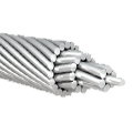
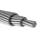
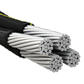
Aluminum conductors dominate the power transmission market due to their high strength-to-weight ratio and electrical conductivity. Their lower density compared to copper allows for long-distance transmission with minimal structural burden. Globally, over 85% of overhead transmission lines use aluminum-based conductors, particularly in the form of All-Aluminum Conductors (AAC), Aluminum Conductor Steel Reinforced (ACSR), and Aluminum Alloy Conductors (AAAC).
| Conductor Type | Primary Use | Conductivity (% IACS) | Tensile Strength (MPa) | Density (g/cm³) |
|---|---|---|---|---|
| AAC | Short spans | ~61 | 90–110 | 2.70 |
| ACSR | Long spans | ~52 | 180–300 | 2.83 |
| AAAC | Urban lines | ~55 | 120–160 | 2.72 |
Source: IEEE Standards; Aluminum Association Reports; CIGRÉ Study Committees
3. The Role of Simulation and Modeling
Simulation and modeling replicate real-world behavior in virtual environments. For aluminum conductors, they allow engineers to assess thermal expansion, mechanical strain, fatigue resistance, and electromagnetic compatibility under varied environmental conditions. Instead of building multiple prototypes, engineers simulate different configurations, materials, and loads to optimize the final design.
By using tools like Finite Element Analysis (FEA) and Computational Fluid Dynamics (CFD), manufacturers can model conductor sag, wind-induced vibration, current capacity, and corrosion over a conductor’s expected 40+ year lifespan. This not only saves cost but also enables data-driven design improvements.
4. Key Simulation Techniques in Conductor Design
Several modeling methods are essential to modern conductor engineering:
Finite Element Analysis (FEA)
FEA simulates mechanical stress and deformation. For instance, sag behavior under variable loads or the tensile effects of wind and ice can be modeled before actual installation.
Thermal Modeling
Predicts heat distribution and dissipation under different current loads. This is vital to avoid hotspots and ensure conductor longevity.
Electromagnetic Field (EMF) Modeling
Used to predict electric field distribution around the conductor. It ensures safety in high-voltage environments and reduces energy loss.
Fatigue and Life Cycle Analysis
Using historical climate data and mechanical loading, engineers simulate wear and estimate time-to-failure to inform maintenance schedules.
5. Case Study: Optimizing AACSR Conductors
A 2022 project led by an energy utility in Germany used ANSYS Mechanical to redesign an AACSR conductor exposed to high wind loads in alpine regions. The model simulated strain, sag, and vibration over 10-year climate data. By altering the aluminum-to-steel ratio and strand configuration, engineers reduced overall sag by 15%, increased fatigue resistance by 28%, and extended estimated service life from 42 to 55 years.
| Metric | Before Optimization | After Optimization |
| Maximum Sag (m) | 3.2 | 2.7 |
| Fatigue Resistance (%) | 100 | 128 |
| Estimated Lifespan (yr) | 42 | 55 |
This case highlighted how virtual testing delivers insights that physical prototyping would take years to gather.
6. Integrating Thermal and Mechanical Models
One of the breakthroughs in simulation is multi-physics modeling. Here, thermal and mechanical models interact. For example, increased current raises conductor temperature, which increases sag. When sag crosses a safety limit, it can lead to outages or contact with trees.
Researchers at the University of Tehran combined thermal and FEA models to predict this interaction in 33 kV lines. Their results showed that an 18% increase in current load during peak demand could raise temperature by 29°C, increasing sag by 24% within 20 minutes. Real-time modeling now guides grid operators in managing load distribution.
7. Advantages of Virtual Prototyping
Simulation saves time and money. Instead of building 5 physical prototypes to test 5 configurations, engineers model each virtually. This reduces development cycles from months to days. It also enhances innovation. Minor design tweaks, like twisting the outer layer or using composite cores, can be quickly validated without manufacturing.
Another benefit is safety. In extreme climates—where icing, high UV, and sandstorms affect conductor behavior—virtual environments simulate these stresses accurately. For instance, an Egyptian utility simulated the behavior of aluminum alloy conductors under desert wind abrasion and sunlight exposure, which led to the selection of UV-resistant coatings and revised installation procedures.
8. Challenges and Limitations
While simulation is powerful, it’s not flawless. Models are only as good as the data and assumptions behind them. Errors in material properties or boundary conditions can produce misleading results. Moreover, simulating rare events like simultaneous wind and ice load requires advanced probabilistic models.
Another issue is computational cost. High-resolution 3D simulations demand large memory and processing power. Small firms may lack access to high-performance computing (HPC) or the technical staff to run these models.
9. Future Trends in Aluminum Conductor Simulation
The next step is integrating Artificial Intelligence. Machine learning models, trained on decades of operational and environmental data, can predict failure before it occurs. Combined with Digital Twins, utilities can monitor and simulate each conductor segment in real time.
Additive manufacturing also enters the picture. Simulations now test how 3D-printed composite-aluminum hybrid cores perform under stress. These cores could revolutionize how conductors are made, reducing both weight and resistance.
| Trend | Application |
| Digital Twin Technology | Real-time simulation of conductor health |
| Machine Learning | Predictive maintenance and anomaly detection |
| 3D Printed Cores | Lightweight, custom geometry designs |
10. Conclusion
Simulation and modeling are reshaping how aluminum conductors are designed, tested, and deployed. From cutting development time to improving performance in extreme environments, these tools provide unmatched insight. With real-world applications validating their impact, it’s clear that virtual testing is no longer optional—it’s essential.
As power demands grow and climate challenges intensify, forward-thinking manufacturers and utilities will rely more on simulation to ensure safe, efficient, and sustainable power delivery.
11. References
IEEE Power & Energy Society. (2023). Aluminum Conductor Applications in Overhead Lines. CIGRÉ Study Committee B2. (2021). Overhead Lines Performance and Modeling Techniques. ANSYS Inc. (2022). High Voltage Conductor Simulation Report. University of Tehran, Faculty of Engineering. (2023). Integrated Thermal-Mechanical Conductor Modeling. Aluminum Association. (2022). Aluminum Electrical Conductor Handbook. ABB Technical Reports. (2021). Predictive Maintenance Using AI in Transmission Lines.



No comment