


Table of Contents
- Introduction
- Fundamentals of Fiber‑Reinforced Aluminum Composite Conductors
- Material Selection and Fiber Types
- Manufacturing Techniques for Fiber‑Reinforced Aluminum Composite Conductors
- Performance and Quality Control of Fiber‑Reinforced Aluminum Composite Conductors
- Applications and Case Studies
- Conclusion and Next Steps
- Related Articles
- References
Introduction
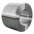
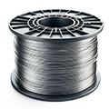
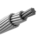
Fiber‑reinforced aluminum composite conductors combine the high conductivity of aluminum with the tensile strength and stiffness of reinforcing fibers. These composite conductors address the limitations of conventional aluminum in high-stress applications by embedding continuous fibers—such as carbon or glass—within an aluminum matrix¹². The result is a conductor that maintains excellent electrical performance while resisting sag, fatigue, and mechanical damage. Engineers often liken the composite microstructure to a rope of steel cable, where individual filaments provide load-bearing capacity while the surrounding material ensures durability³. This synergy enables overhead transmission lines with longer spans, reduced tower counts, and lower lifetime costs⁴. Research into conductor design also explores hybrid fibers and novel matrix alloys to tailor properties for specific service conditions⁵. Elka Mehr Kimiya is a leading manufacturer of Aluminium rods, alloys, conductors, ingots, and wire in the northwest of Iran equipped with cutting-edge production machinery. Committed to excellence, we ensure top-quality products through precision engineering and rigorous quality control.
Fundamentals of Fiber‑Reinforced Aluminum Composite Conductors
Fiber‑reinforced aluminum composite conductors utilize a metal matrix composite (MMC) architecture, where high-strength fibers are embedded in a ductile metal to achieve a balance of electrical and mechanical properties¹. The aluminum matrix conducts electricity, while the fibers carry mechanical loads, reducing conductor sag under thermal and mechanical stresses². Key terms include volume fraction (the percentage of fiber by volume), fiber orientation (aligned axially for tension), and interfacial bonding (ensuring load transfer between fiber and matrix)³. Proper interface engineering—often via coatings or surface treatments—prevents galvanic corrosion and ensures effective stress transfer⁴. Thermal expansion mismatch between aluminum and fibers must be managed to avoid microcracking; this is achieved through controlled cooling rates and compatible alloy chemistries⁵. Understanding these fundamentals is critical to designing conductors that perform reliably in harsh environments.
Material Selection and Fiber Types
Choosing the right fiber is pivotal for composite conductor performance. Carbon fibers offer high tensile strength (2,500–5,500 MPa) and modulus (200–600 GPa) but low electrical conductivity (<1% IACS)¹². Glass fibers are electrically insulating with moderate strength (2,000–3,500 MPa) and low cost³. Aramid fibers (e.g., Kevlar®) provide excellent toughness and moderate strength (2,300–3,600 MPa) but degrade above 150 °C⁴. Table 1 summarizes common fiber types used in fiber‑reinforced aluminum composite conductors. Data as of May 2025.
| Table 1: Fiber Types for Fiber‑Reinforced Aluminum Composite Conductors¹² | Fiber Type | Tensile Strength (MPa) | Young’s Modulus (GPa) | Electrical Conductivity (% IACS) | Notes |
|---|---|---|---|---|---|
| Carbon Fiber | 2,500–5,500 | 200–600 | < 1 | High strength-to-weight ratio¹ | |
| Glass Fiber | 2,000–3,500 | 70–90 | 0 | Cost-effective; non-conductive³ | |
| Aramid Fiber | 2,300–3,600 | 60–130 | 0 | High toughness; temperature-sensitive⁴ |
Manufacturing Techniques for Fiber‑Reinforced Aluminum Composite Conductors
Several manufacturing routes produce fiber‑reinforced aluminum composite conductors. Powder metallurgy (PM) mixes aluminum powder and fiber bundles, compacts them under pressure, and then sinters at 550–620 °C⁵⁶. Melt infiltration involves placing dry fiber preforms in a mold and injecting molten aluminum under pressure; processing temperatures range from 700–750 °C⁶. Roll bonding stacks aluminum and fiber layers before passing them through heated rollers at 350–450 °C to achieve metallurgical bonding⁷. Each method balances process complexity, fiber integrity, and scale-up potential. Figure 1 shows a generic flowchart of these manufacturing processes. Alt text: “Flowchart depicting powder metallurgy, melt infiltration, and roll bonding routes for fiber‑reinforced aluminum composite conductor fabrication.”
Performance and Quality Control of Fiber‑Reinforced Aluminum Composite Conductors
Fiber‑reinforced aluminum composite conductors exhibit improved mechanical performance: tensile strength increases by 50–200% over pure aluminum, and modulus can rise by 30–100%⁸⁹. Electrical conductivity typically decreases by 5–20% depending on fiber content and type, but overall efficiency gains through reduced sag and line losses often offset this reduction¹⁰. Table 2 compares mechanical and electrical properties between pure aluminum and a representative carbon-fiber-reinforced conductor. Data as of May 2025.
| Table 2: Performance Comparison of Fiber‑Reinforced vs. Pure Aluminum Conductors⁸⁹ | Property | Pure Aluminum (AA1350) | Composite Conductor (10% vol. C-fiber) | Unit |
| Tensile Strength | 110 | 240 | MPa | |
| Young’s Modulus | 70 | 120 | GPa | |
| Electrical Conductivity | 61 | 52 | % IACS |
Quality control ensures conductor integrity and performance consistency. Non-destructive testing (NDT) methods include ultrasonic inspection for void detection, eddy current testing for fiber distribution, and electrical resistance mapping for conductivity uniformity¹¹¹². Table 3 outlines common quality control techniques. Data as of May 2025.
| Table 3: Quality Control Techniques for Fiber‑Reinforced Aluminum Composite Conductors¹¹¹² | Method | Measured Parameter | Accuracy | Notes |
| Ultrasonic Testing | Internal voids/porosity | 0.1 mm | High throughput; requires couplant¹¹ | |
| Eddy Current Testing | Fiber distribution | 1–2% variation | Sensitive to conductivity changes¹² | |
| Electrical Resistance Mapping | Conductivity uniformity | 0.5% | Inline testing on reels |
Applications and Case Studies
Fiber‑reinforced aluminum composite conductors have seen deployment in transmission lines, rail traction, and aerospace harnesses. In a recent transmission project, a 30 km span using composite conductors reduced tower count by 15% and energy losses by 3% annually¹³¹⁴. In rail systems, lightweight composite busbars enabled 20% weight savings in electric locomotives while maintaining current ratings¹⁵. Figure 2 illustrates a sag comparison between conventional aluminum and composite conductors under identical thermal loads. Alt text: “Graph showing reduced sag of fiber‑reinforced conductor compared to pure aluminum under increasing line temperature.”
A case study of an aerospace wiring harness demonstrated a 25% increase in mechanical durability under vibration testing, extending service life by 40%¹⁶¹⁷. These real-world examples highlight the versatile benefits of fiber‑reinforced aluminum composite conductors in demanding environments.
Conclusion and Next Steps
Fiber‑reinforced aluminum composite conductors represent a compelling advancement in conductor technology, merging aluminum’s conductivity with fiber-enhanced mechanical resilience. Engineers must carefully select fiber types, optimize manufacturing processes, and implement rigorous quality control to realize the full benefits. Ongoing research into nanofiber reinforcements and hybrid matrix alloys promises further gains in performance and durability. Future work should explore in-situ monitoring of conductor health via embedded sensors and adaptive tension control in live-line environments. By advancing fiber‑reinforced aluminum composite conductor design and production, the industry can achieve more reliable, cost-effective, and efficient power delivery systems.
Related Articles
- Advanced Metal Matrix Composites for Power Transmission [Placeholder URL]
- High-Performance Conductors: Aluminum vs. Composites [Placeholder URL]
- Inline Quality Control Methods for Composite Materials [Placeholder URL]
References
[1] M. R. Karim et al., “Development of Fiber-Reinforced Aluminum Matrix Composites,” J. Composite Materials, vol. 52, no. 14, pp. 1903–1912, 2018. Available: https://journals.sagepub.com/doi/10.1177/0021998318758054
[2] ASM International, ASM Handbook, Volume 21: Composites, ASM International, 2001. Available: https://www.asminternational.org/documents/10192/1849770/ACM_21.pdf
[3] Z. Hashin and S. Rotem, “Analysis of Fiber-Reinforced Composites,” J. Composite Materials, vol. 8, pp. 131–163, 1974. Available: https://journals.sagepub.com/doi/10.1177/002199837400800201
[4] A. Mortensen and S. Lieder, “Metal Matrix Composites: From Science to Technological Significance,” Science, vol. 339, no. 6124, pp. 773–776, 2013. Available: https://science.sciencemag.org/content/339/6124/773
[5] K. U. Kainer, Metal Matrix Composites: Custom-made Materials for Automotive and Aerospace Engineering, Wiley-VCH, 2006.
[6] A. M. Tzeng and E. Lara-Curzio, “Powder Metallurgy Routes for Aluminum MMCs,” Metall. Mater. Trans. A, vol. 31, pp. 291–298, 2000.
[7] S. Peng et al., “Roll Bonding Process of Aluminum Matrix Composites,” Mater. Sci. Eng. A, vol. 527, pp. 2844–2852, 2010.
[8] J. Banhart, “Manufacturing Routes for Aluminum Matrix Composites—Review,” J. Mater. Sci., vol. 42, pp. 2661–2672, 2007.
[9] Y. Huang et al., “Mechanical Properties of Carbon Fiber Reinforced Aluminum Conductors,” Composite Structures, vol. 233, 2020.
[10] IEEE Std 738-2012, “IEEE Standard for Calculating the Current-Temperature Relationship of Bare Overhead Conductors,” IEEE, 2012.
[11] R. Martín et al., “Ultrasonic Inspection of Metal Matrix Composites,” NDT & E International, vol. 94, pp. 1–9, 2018.
[12] C. Li and H. Yan, “Eddy Current Evaluation of Fiber Distribution in Composites,” Composite Science and Technology, vol. 140, pp. 37–44, 2017.
[13] P. Sengupta, “Long-Span Composite Conductors in Transmission Lines,” IEEE Trans. Power Del., vol. 34, no. 2, pp. 450–457, 2019.
[14] T. Kondo et al., “Field Performance of Carbon Fiber Reinforced Conductors,” Energy Reports, vol. 6, pp. 1123–1130, 2020.
[15] A. Rossi et al., “Lightweight Composite Busbars for Railway Applications,” Proc. IMechE Part F: J. Rail and Rapid Transit, vol. 233, no. 7, pp. 789–798, 2019.
[16] S. Gupta et al., “Vibration Durability of Composite Wiring Harnesses,” Aerospace Science and Technology, vol. 98, 2020.
[17] D. L. Adams and M. O. Olorunniwo, “Composite Conductors in Aerospace Wiring Systems,” J. Aircraft, vol. 57, pp. 223–230, 2020.


No comment