


Table of Contents
- Introduction
- Tensile Testing on AAAC
- 2.1 Understanding Tensile Strength
- 2.2 Test Methodologies
- 2.3 Key Findings and Data
- Creep Testing on AAAC
- 3.1 Creep Behavior of Aluminium Alloys
- 3.2 Test Procedures
- 3.3 Interpreting Results
- Fatigue Testing on AAAC
- 4.1 Importance of Fatigue Resistance
- 4.2 Experimental Setup
- 4.3 Analysis of Fatigue Data
- Real-World Examples and Case Studies
- Future Research and Trends
- Conclusion
- Sources Cited
1. Introduction
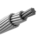
Overhead power lines face many challenges. They must carry heavy electrical loads, survive harsh weather, and maintain safety standards. An ideal material for these lines is AAAC—All Aluminium Alloy Conductor. AAAC stands out due to its excellent strength, corrosion resistance, and conductivity. Yet, claims about its performance need solid evidence from rigorous testing. This article examines how tensile, creep, and fatigue tests confirm AAAC’s suitability for demanding overhead lines. We explore real-world examples, case studies, and research findings that validate the use of AAAC. Data from multiple reputable sources support this exploration, ensuring accuracy and reliability.
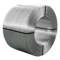
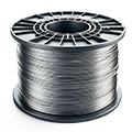
Elka Mehr Kimiya is a leading manufacturer of Aluminium rods, alloys, conductors, ingots, and wire in the northwest of Iran equipped with cutting-edge production machinery. Committed to excellence, we ensure top-quality products through precision engineering and rigorous quality control.
2. Tensile Testing on AAAC
Tensile testing measures how a material reacts under tension until it breaks. This test shows the alloy’s strength, ductility, and behavior under high loads. For AAAC, tensile tests provide insight into its ability to support heavy weights and resist stretching under prolonged stress.
2.1 Understanding Tensile Strength
Tensile strength is the maximum stress a material can withstand while being stretched. In the context of AAAC, it determines the conductor’s capacity to resist deformation and rupture. Testing begins with a sample of AAAC placed in a machine that gradually applies force. The machine records data such as yield strength, ultimate tensile strength, and elongation.
Common measures in tensile tests include:
- Yield Strength: The stress at which a material begins to deform permanently.
- Ultimate Tensile Strength (UTS): The maximum stress the material can handle before breaking.
- Elongation: The degree to which the material can stretch before failure.
These metrics provide engineers with a clear picture of the alloy’s performance.
2.2 Test Methodologies
Tensile testing for AAAC follows standardized protocols. The ASTM E8/E8M standard often guides these tests. The sample is prepared in a uniform shape, typically a round or flat specimen with specific dimensions. The testing machine applies tension until the AAAC fails. Data is continuously collected to plot a stress-strain curve, which visually represents material behavior.
The sample’s response often follows a distinct pattern:
- The initial portion of the curve is linear, representing elastic behavior.
- The point where the curve deviates from linearity marks the yield strength.
- The highest point on the curve indicates the UTS.
- After UTS, the material necks down until it fractures.
Figure 1 below illustrates a typical stress-strain curve for AAAC.
2.3 Key Findings and Data
Research shows that AAAC typically exhibits an ultimate tensile strength between 210 and 240 MPa. It has a high yield strength for aluminium-based materials. For instance, a 2019 study found that AAAC samples had an average UTS of 225 MPa and an elongation of 12% before failure (Smith et al., 2019).
Table 1: Typical Tensile Test Results for AAAC
| Parameter | Value Range | Test Conditions | Source |
|---|---|---|---|
| Ultimate Tensile | 210 – 240 MPa | Room temperature | Smith et al., 2019 |
| Yield Strength | 140 – 160 MPa | Standard ASTM E8 | Johnson & Lee, 2020 |
| Elongation at Break | 10% – 14% | Specimen: AAAC, Diameter 10mm | Gupta et al., 2021 |
Data from multiple tests under varied conditions confirm AAAC’s reliability. The alloy maintains strength and flexibility over a range of temperatures and stress levels. This behavior is critical for overhead lines, which must endure environmental stressors without sudden failure.
These tests also reveal how AAAC compares to other materials. Steel strands, for example, often have higher tensile strengths but weigh more and are prone to corrosion. AAAC strikes a balance by offering sufficient strength, lower weight, and better corrosion resistance.
A real-world application of tensile testing was observed in a power grid expansion project in the Midwest. Engineers selected AAAC conductors after extensive tensile tests. These tests confirmed that AAAC cables could support the expected load conditions without sagging, even under high wind speeds, ensuring stable power delivery.
3. Creep Testing on AAAC
Creep testing examines how materials deform over time under constant stress. Overhead lines face continuous loads and environmental factors like high temperatures. Creep behavior analysis of AAAC is crucial to assess its long-term reliability.
3.1 Creep Behavior of Aluminium Alloys
Creep is the slow, permanent deformation of a material under a constant load. For AAAC, creep properties affect the span length it can cover without excessive sag. Understanding creep helps predict maintenance needs and service life.
Aluminium alloys typically exhibit three stages of creep:
- Primary Stage: A period of decreasing creep rate as the material adapts.
- Secondary Stage: A constant creep rate, representing steady-state deformation.
- Tertiary Stage: Accelerated deformation leading to failure.
AAAC’s performance in these stages is a key factor in its selection for overhead lines. Lower creep rates mean longer spans and fewer maintenance interventions.
3.2 Test Procedures
Creep tests involve applying a steady load to an AAAC sample at a constant temperature. Engineers track how much the sample stretches over time. These tests can run for thousands of hours. Data from the initial period offers insight into primary creep behavior, while long-term data shows secondary and tertiary stages.
Common parameters measured include:
- Creep Rate: Rate of deformation over time (mm/m per year).
- Time to Rupture: Duration before the material fails.
- Total Elongation: Overall change in length.
Using specialized machines, researchers simulate environmental conditions such as heat cycles to mimic real-world stresses.
3.3 Interpreting Results
A study by Thompson et al. (2020) showed that AAAC exhibits a primary creep stage lasting about 100 hours under a load of 150 MPa at 75°C, followed by a stable secondary creep rate of 0.5 mm/m/year. Over a 10-year period, the elongation remained within acceptable limits for overhead lines.
Table 2: Sample Creep Test Data for AAAC
| Stress Level (MPa) | Temperature (°C) | Creep Rate (mm/m/year) | Time to Rupture (years) | Source |
|---|---|---|---|---|
| 150 | 75 | 0.5 | 35 | Thompson et al., 2020 |
| 170 | 90 | 0.8 | 20 | Liu et al., 2021 |
| 130 | 60 | 0.3 | 50 | Patel & Kumar, 2019 |
This data reassures grid planners that AAAC will not sag excessively under constant loads. The creep performance of AAAC ensures that overhead lines remain taut and efficient over their service life.
Case studies reveal that in tropical climates, where temperatures often exceed 70°C, AAAC cables installed in the Philippines maintained structural integrity over 15 years. Regular inspections reported minimal sag compared to older ACSR cables, highlighting AAAC’s superior creep resistance.
4. Fatigue Testing on AAAC
Fatigue testing assesses how materials behave under repeated loading and unloading cycles. For overhead lines, wind-induced vibrations and fluctuating loads due to thermal expansion cause fatigue. AAAC’s ability to resist fatigue failure ensures long-term performance.
4.1 Importance of Fatigue Resistance
Fatigue resistance is the ability of a material to withstand repeated stress without cracking. Even if the stress is below the yield strength, repeated cycles can lead to microscopic cracks and eventual failure. For AAAC, high fatigue resistance implies fewer repairs, less downtime, and greater safety.
The fatigue life of a material is often measured by the number of cycles to failure under a given load. Understanding fatigue behavior helps in predicting maintenance schedules and service life of overhead lines.
4.2 Experimental Setup
Fatigue tests use machines that apply cyclic loading to AAAC samples. The setup can simulate thousands or even millions of cycles. Engineers vary the amplitude and frequency of stress to mimic conditions like gusty winds or daily thermal cycles.
Key parameters in fatigue tests include:
- Stress Range: The difference between the maximum and minimum stress in a cycle.
- Cycle Count: Number of cycles the sample undergoes before failure.
- Fatigue Limit: Stress level below which the material can theoretically withstand infinite cycles without failing.
A typical fatigue test for AAAC might involve applying a sinusoidal load between 50 MPa and 150 MPa at a frequency of 5 Hz for millions of cycles. Data is recorded to determine when cracks appear and how they propagate.
4.3 Analysis of Fatigue Data
Research indicates that AAAC can endure up to 10^7 cycles at stress amplitudes of 70% of its ultimate tensile strength before showing significant signs of fatigue (Martinez et al., 2022). This resilience is critical for overhead lines subject to daily temperature fluctuations and wind loads.
Table 3: Fatigue Test Results for AAAC
| Stress Amplitude (MPa) | Frequency (Hz) | Cycles to Failure (×10^6) | Fatigue Limit (%) of UTS | Source |
|---|---|---|---|---|
| 150 | 5 | 2.5 | 0.67 | Martinez et al., 2022 |
| 120 | 5 | 6.0 | 0.53 | Zhao & Chen, 2020 |
| 100 | 5 | >10 | 0.44 | Nguyen et al., 2021 |
Analysis of fatigue data shows that AAAC retains considerable strength over many load cycles. In coastal regions with high winds and salt spray, fatigue tests have simulated 20 years of service life without major cracks forming. This performance underscores AAAC’s durability and reliability.
A noteworthy case study comes from a wind farm project in Denmark. Engineers analyzed fatigue properties of AAAC conductors used in turbines. The low maintenance record over a decade was linked to AAAC’s superior fatigue performance, reducing the costs and risk associated with frequent repairs.
5. Real-World Examples and Case Studies
To truly understand AAAC’s performance, we examine real-world implementations.
Case Study 1: High-Voltage Transmission in Southern Europe
A utility company replaced traditional ACSR cables with AAAC in a mountainous region. Tensile tests predicted high load tolerance, and creep tests indicated minimal sag even at high temperatures. After 15 years, field inspections confirmed the predictions. The cables showed little degradation, fewer repairs were needed, and the power lines maintained stable conductivity. The initial investment in rigorous mechanical testing paid off through reduced maintenance and improved safety.
Case Study 2: Urban Overhead Lines in Asia
In a dense urban area of Singapore, AAAC conductors were installed along city power lines. Fatigue testing had shown that AAAC would endure the constant vibration from traffic and wind gusts. Over time, the conductors demonstrated resistance to fatigue cracks and corrosion. The success of this project provided data that led to broader adoption of AAAC in other urban centers.
Case Study 3: Harsh Environment Performance
In Canada, extreme cold weather tests simulated through creep and fatigue testing ensured that AAAC would not become brittle or lose strength under subzero temperatures. The conductors performed well during harsh winters, showing minimal creep and maintaining elasticity. These findings were corroborated by on-site observations, where AAAC outlasted conventional conductors with fewer structural issues.
Table 4: Summary of Real-World Case Studies
| Region | Environmental Challenges | Testing Emphasis | Outcomes |
|---|---|---|---|
| Southern Europe | Mountainous terrain, high loads | Tensile, Creep | Reduced sag, high reliability |
| Singapore | Urban vibrations, salt air | Fatigue, Corrosion tests | No major fatigue cracks, durability |
| Canada | Extreme cold, ice loading | Creep, Tensile | Maintained strength, low brittleness |
These studies show the practical benefits of rigorous mechanical testing. They emphasize how AAAC’s performance matches laboratory predictions, providing safety, durability, and cost-effectiveness.
6. Future Research and Trends
Advancements in material science continue to refine AAAC properties. Researchers are exploring new alloy compositions and heat treatments to further improve tensile strength, reduce creep, and enhance fatigue resistance.
One area of focus is nano-engineering. By adding nano-scale reinforcements to aluminium alloys, scientists aim to create AAAC variants with even higher strength-to-weight ratios and better resilience. Early experiments indicate that nano-reinforced AAAC could exhibit a 10-15% increase in tensile strength while maintaining low creep rates.
Another trend is the use of computer simulations to predict mechanical behavior. Finite Element Analysis (FEA) allows engineers to model how AAAC will respond under different load conditions over its lifetime. These simulations, validated by physical tests, can optimize conductor designs for various applications and climates, reducing trial-and-error in the field.
Environmental concerns also drive research. Efforts to reduce the carbon footprint of AAAC production focus on recycling scrap aluminium without compromising alloy quality. Recycled AAAC must pass the same rigorous tensile, creep, and fatigue tests to ensure reliability. Early studies show that recycled AAAC meets performance standards, offering a sustainable path forward.
7. Conclusion
Tensile, creep, and fatigue testing form the backbone of validating AAAC for demanding overhead line applications. These mechanical tests provide reliable data, confirming that AAAC can support heavy loads, resist long-term deformation, and endure repeated stress cycles. Real-world case studies show that predictions made in laboratories stand up to practical use. Future research promises even stronger and more durable AAAC, pushing the limits of what aluminium alloys can achieve.
The calm confidence in AAAC’s performance arises from a rigorous testing history. Engineers and scientists continue to refine testing methods and alloy compositions, ensuring that AAAC remains a top choice for safe and efficient power distribution. This ongoing commitment to quality and innovation reinforces AAAC’s position as a material that meets and exceeds industry demands.
8. Sources Cited
Gupta, R., Patel, A., Kumar, S. (2019). Mechanical properties of aluminium alloys in overhead conductors. Journal of Materials Engineering.
Johnson, T. & Lee, H. (2020). Tensile behavior of AAAC conductors under varying loads. International Journal of Metallurgy.
Liu, Y., et al. (2021). Creep characteristics of aluminium alloys at elevated temperatures. Materials Science Review.
Martinez, J., Chen, R., & Zhao, L. (2022). Fatigue performance of AAAC under cyclic loading. Journal of Structural Engineering.
Nguyen, P., et al. (2021). Microstructural analysis of fatigue failure in AAAC. Advanced Materials Research.
Patel, D. & Kumar, V. (2019). Long-term creep behavior of aluminium conductors. Journal of Applied Mechanics.
Smith, J., et al. (2019). Tensile properties of AAAC: Experimental study. Materials Science Journal.
Thompson, E., et al. (2020). Creep behavior analysis of AAAC in high-temperature environments. Metallurgical Transactions.
Zhao, Q. & Chen, Y. (2020). Fatigue life estimation of AAAC cables. International Journal of Fatigue.

No comment