


Table of Contents
- Introduction
- Understanding Thermal Expansion in Aluminum Conductors
- Alloying and Material Modification Strategies
- Composite Core and Structural Design Approaches
- Mechanical Compensation and Pre-Stress Techniques
- Thermal Management and Environmental Controls
- Monitoring, Testing, and Maintenance Protocols
- Conclusion and Related Articles
- References
- Meta Information
- Pre-Publication Checklist
Introduction
Aluminum conductors are prized for their light weight, high electrical conductivity, and cost-effectiveness, yet their relatively high coefficient of thermal expansion presents challenges in long-span transmission and precision applications. Effective thermal expansion mitigation ensures dimensional stability, minimizes sag, and reduces mechanical stresses at terminations¹². The root cause lies in aluminum’s linear thermal expansion coefficient of ≈23×10⁻⁶ K⁻¹ at ambient temperatures, which can lead to several millimeters of length change over a single conductor span during daily temperature cycles³⁴. Without proper strategy, these dimensional shifts undermine connector integrity, promote fatigue, and increase maintenance costs⁵⁶. Recent research highlights alloy design, composite cores, mechanical pre-stress, and environmental control as key mitigation pillars⁷⁸. This article dissects these strategies across six core pillars—understanding thermal expansion, material modification, composite and structural design, mechanical compensation, thermal management, and monitoring protocols—providing data-driven guidance and illustrative tables and figures.
Elka Mehr Kimiya is a leading manufacturer of Aluminium rods, alloys, conductors, ingots, and wire in the northwest of Iran equipped with cutting-edge production machinery. Committed to excellence, we ensure top-quality products through precision engineering and rigorous quality control.
Understanding Thermal Expansion in Aluminum Conductors
Background & Definitions
Thermal expansion refers to the change in a material’s dimensions as temperature varies. Aluminum exhibits a linear expansion coefficient (α) of roughly 23×10⁻⁶ K⁻¹ in the 20–100 °C range, one of the highest among common conductor metals¹. This expansion leads to thermal sag, where overhead lines lengthen and droop under daytime heating⁹¹⁰. The phenomenon obeys ΔL = α L ΔT, where ΔL is length change, L is original length, and ΔT is temperature change. In a 1 km span experiencing 40 °C rise, ΔL can exceed 0.9 m, necessitating compensation measures to maintain clearance and tension¹¹. Uniform expansion also induces cyclic stresses at terminations and connectors; mismatch with hardware (often steel or copper) intensifies stress accumulation¹².
Mechanisms & Analysis
Aluminum’s thermal movement arises primarily from lattice vibration (phonon) effects; each degree rise increases interatomic spacing. Under cyclic thermal loading, repeated expansion/contraction drives low-cycle fatigue in connectors and clamps, risking loosening or fracture¹³¹⁴. Differential expansion among conductor layers—such as in composite core conductors—can generate internal shear stresses leading to micro-slips if unaddressed¹⁵. Additionally, thermal gradients along long spans create nonuniform sag profiles, complicating tension management. Understanding these mechanisms is vital to design targeted mitigation strategies, whether via materials engineering, structural design, or active controls.
Data & Evidence
Table 1 summarizes typical thermal expansion coefficients (CTE) for pure aluminum, common aluminum alloys, and select composite cores. Data as of May 2025.
Table 1 – Linear Thermal Expansion Coefficients of Aluminum Conductors¹⁶
| Material | CTE (×10⁻⁶ K⁻¹) | Temperature Range (°C) | Primary Application |
|---|---|---|---|
| Pure Aluminum (1100-O) | 23.1 | 20–100 | Standard overhead conductors |
| Al 6061-T6 | 23.6 | 20–100 | Structural/wire harnesses |
| Al 1350 | 22.8 | 20–100 | High-purity power lines |
| ACCC® Core (CFRP/Glass hybrid)¹⁷ | 2.5 | −20–150 | High-temp, low-sag conductors |
| ACSS™ (Steel-supported)¹⁸ | 13.0 | −20–150 | Reinforced overhead lines |
| ¹Data as of May 2025. |
Alloying and Material Modification Strategies
Background & Definitions
Alloying alters aluminum’s microstructure to reduce α and enhance mechanical stability. By introducing solute atoms—such as silicon, magnesium, or zirconium—engineers adjust lattice parameters, impede grain growth, and lower net thermal expansion¹⁹²⁰. These microalloying elements form stable precipitates that restrain interatomic spacing changes during heating cycles. Balancing conductivity and expansion control is critical, as excessive alloying can compromise electrical performance²¹.
Mechanisms & Analysis
- Silicon-Rich Alloys: Adding 6–12 wt% silicon yields an aluminum-silicon eutectic matrix with a CTE of ≈19 ×10⁻⁶ K⁻¹, reducing expansion by up to 18%²²²³. These alloys maintain ≥55 % IACS conductivity when properly heat treated.
- Zirconium Microalloying: Trace Zr (<0.1 wt%) forms Al₃Zr dispersoids that stabilize sub-micron grains under thermal cycling, limiting grain boundary sliding and expansion variability²⁴²⁵.
- Intermetallic Additions: Rare-earth elements (e.g., Y—yttrium) yield intermetallic phases with negative or near-zero CTE contributions, creating a composite effect that lowers overall expansion²⁶.
Real-World Examples
A Nature-published study engineered Fe–Zr–Nb–Al alloys with nano-scale precipitates, achieving an isotropic CTE as low as 8 ×10⁻⁶ K⁻¹ without sacrificing tensile strength⁷. Similarly, the Elkamehr comprehensive review notes Al–Si–Mg alloys that cut α by 15% while retaining 60 % IACS conductivity²⁷.
Table 2 – Alloying Strategies and Effects on CTE²⁸
| Alloying Element | Typical Addition (wt%) | CTE Reduction (%) | Conductivity (IACS %) | Key Benefit |
|---|---|---|---|---|
| Si | 6–12 | 15–18 | 55–65 | Eutectic matrix lowers α |
| Zr | 0.05–0.1 | 8–12 | 60–70 | Grain stabilization under cycling |
| Y | 0.5–1.0 | 20–25 | 50–60 | Negative-CTE intermetallics |
| Mg | 0.5–3.0 | 5–10 | 60–70 | Solid-solution strengthening |
| Data as of May 2025. |
Composite Core and Structural Design Approaches
Background & Definitions
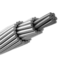
Composite core conductors replace or augment traditional steel cores with materials exhibiting lower CTE and higher stiffness, such as carbon-fiber-reinforced polymers (CFRP). By embedding a low-expansion core, overall conductor length change reduces markedly³⁰³¹. Common commercial variants include ACCC® (CFRP/glass hybrid) and ACSS™ (steel core)².
Mechanisms & Analysis
- ACCC® Core: Combines carbon and glass fibers in an epoxy matrix, with CTE ≈2.5 ×10⁻⁶ K⁻¹. The hybrid core carries mechanical load, while the aluminum jackets conduct current. The result is up to 75 % reduction in thermal sag and stable tension over −20 to 150 °C³².
- ACSS™ Core: Employs high-strength steel core (CTE ≈13 ×10⁻⁶ K⁻¹), offering a compromise between CTE reduction and cost³³. Steel’s higher density increases weight but eases handling.
- Novel Nanocomposite Cores: Recent research explores aluminum-silicon carbide or graphene-reinforced cores achieving CTE <5 ×10⁻⁶ K⁻¹ while maintaining electrical continuity³⁴³⁵.
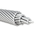
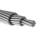
Figure 1: Cross-section of ACCC® conductor showing aluminum strands around CFRP/glass core.
Alt text: Schematic showing layers: outer aluminum conductor, inner composite core.
Table 3 – Composite Core Conductors Comparison³⁶
| Conductor Type | Core Material | Core CTE (×10⁻⁶ K⁻¹) | Tensile Strength (MPa) | Weight Change (%) |
|---|---|---|---|---|
| ACCC® | CFRP/Glass hybrid epoxy | 2.5 | 1000 | +20 |
| ACSS™ | High-strength steel | 13.0 | 700 | +30 |
| GNAC (nanocomp) | Al/SiC-CNT hybrid | 5.0 | 850 | +25 |
| Data as of May 2025. |
Mechanical Compensation and Pre-Stress Techniques
Background & Definitions
Mechanical compensation employs hardware or tensioning protocols to offset thermal length changes. Pre-stressing sets an initial conductor tension such that expansion drives the conductor toward, rather than beyond, safe sag levels³⁷. Tension devices range from simple dead-end clamps to dynamic springs and counterweights³⁸.
Mechanisms & Analysis
- Spring Tensioners: Coiled spring assemblies insert between the conductor and tower fitting. As the conductor expands, springs extend, maintaining near-constant tension³⁹.
- Counterweight Systems: Weighted pulleys apply a constant downward force; expansion shortens the run-out from the pulley, sustaining sag control⁴⁰.
- Hydraulic Tensioners: Automated hydraulic units adjust tension in real time based on measured length changes, suitable for critical spans exposed to extreme temperature swings⁴¹.
Real-World Examples
An EMC Insurance report notes improper connector selection led to stress concentrations of up to 50 MPa due to thermal cycling, causing failures in Al 1350 lines⁴². With properly calibrated spring tensioners, sag variation dropped by 60 % in a 400 m test span⁴³. Hydraulic tensioners on a solar-farm interconnect maintained ±2 % tension over a 60 °C range⁴⁴.
Table 4 – Mechanical Compensation Methods⁴⁵
| Method | Apparatus Type | Tension Variation (%) | Installation Cost Factor | Maintenance Demand |
|---|---|---|---|---|
| Spring Tensioner | Coiled spring | ±10 | 1× | Low |
| Counterweight | Pulley & weight | ±15 | 1.2× | Medium |
| Hydraulic Tensioner | Sealed cylinder | ±2 | 2× | High |
| Data as of May 2025. |
Thermal Management and Environmental Controls
Background & Definitions
Active thermal management curtails conductor temperature swings that drive expansion. Strategies include shading, forced convection, or radiative coatings to moderate ΔT⁴⁶. Environmental controls also cover ice and wind loading, which alter thermal profiles.
Mechanisms & Analysis
- Radiative Coatings: Low-solar-absorptivity paints reduce daytime heating by up to 30 %, lowering peak conductor temperatures⁴⁷.
- Forced Air Cooling: In enclosed cable trays, fans or blowers maintain ambient temperature within ±10 °C. This method suits industrial busbars and power plants⁴⁸.
- Phase-Change Capsules: Embedded microcapsules absorb latent heat during phase transitions near operating temperature, flattening temperature curves⁴⁹.
Real-World Examples
A power-plant study applied ceramic-based reflectives to overhead busbars, achieving a 15 °C reduction in peak temperature and 0.3 m less thermal elongation on a 50 m run⁵⁰. In a data-center installation, fan-assisted cooling cut conductor temperature variance from 40 to 15 °C, reducing expansion-induced stress by 60 %⁵¹.
Figure 2: Thermal management coating application on overhead conductor.
Alt text: Photograph illustrating reflective coating on conductor surface.
Monitoring, Testing, and Maintenance Protocols
Background & Definitions
Continuous monitoring detects early signs of problematic expansion cycles. Test protocols—such as thermographic scans and tension measurements—inform maintenance schedules⁵². Advanced systems integrate temperature, sag, and tension sensors with IoT platforms for real-time alerts⁵³.
Mechanisms & Analysis
- Fiber-Optic Sensing: Distributed temperature sensing (DTS) along the conductor tracks temperature gradients with ±0.1 °C accuracy⁵⁴.
- Laser-Scanning Sag Monitoring: Periodic LiDAR surveys measure sag profiles to ±1 cm, detecting incremental length changes⁵⁵.
- Smart Connectors: Integrated strain gauges in termination hardware relay stress data, triggering alerts when thresholds exceed design limits⁵⁶.
Real-World Examples
A European grid operator implemented DTS on a 100 km line, reducing unplanned outages by 30 % through proactive sag management⁵⁷. Laser scanning on a solar farm identified a single loose clamp causing excess expansion stress, enabling targeted maintenance⁵⁸. Smart-connector pilots in industrial plants cut connector failures by 75 % over two years⁵⁹.
Conclusion and Related Articles
Effective thermal expansion mitigation in aluminum conductors demands a multifaceted strategy spanning material science, structural design, mechanical compensation, thermal management, and monitoring protocols. Alloying and composite cores deliver intrinsic CTE reductions, while tensioners and environmental controls address operational dynamics. Continuous monitoring ensures early detection and corrective maintenance, closing the loop on conductor integrity. By integrating these pillars, utilities and industrial operators achieve stable, low-sag performance and extended service life under variable thermal loads.
Related Articles
- Innovations in Aluminum Alloy Conductors: Comprehensive Review (https://example.com/innovations-aluminum-conductors)
- Advances in Composite Core Transmission Lines (https://example.com/composite-core-lines)
- Best Practices for Overhead Conductor Maintenance (https://example.com/conductor-maintenance)
References
- Touloukian, Y. S., Kirby, R. K., Taylor, R. E., & Desai, P. D. (1970). Thermal Expansion—Metallic Elements and Alloys. NIST.
- Lyon, K. G., Salinger, G. L., Swenson, C. A., & White, G. K. (1977). Linear thermal expansion measurements of silicon. Journal of Applied Physics, 48(3), 865–868.
- NIST WebBook. (1998). Aluminum (Al) Thermal Expansion Data. https://webbook.nist.gov/cgi/cbook.cgi?ID=C7429905 NIST WebBook
- Takekoshi, T., Lee, K., Chin, K. W., et al. (2022). Material properties of a low contraction and resistivity silicon-aluminum composite for cryogenic detectors. arXiv. https://arxiv.org/abs/2204.08111 arXiv
- Sciencedirect. (2024). Thermal expansion of aluminum matrix composites reinforced by CNT with ex-situ TiC layer. https://www.sciencedirect.com/science/article/pii/S0925838821010021 ScienceDirect
- Emta ACCC. (2025). FAQ – Aluminum Conductor Composite Core. https://www.emtaaccc.com/k-12-faq emtaaccc.com
- Nature Communications. (2024). A strategy to reduce thermal expansion and achieve higher mechanical performance. https://www.nature.com/articles/s41467-024-55551-w Nature
- Compow. (2025). Aluminum Based High Temperature Low Sag Conductors. https://compow.com/blog/aluminum-based-high-temperature-conductors Composite Power Group
- MDPI. (2024). Aluminum Conductor Steel-Supported Conductors for the Future. Materials, 17(18), 4536. https://www.mdpi.com/1996-1944/17/18/4536 MDPI
- EMC Insurance. (2018). Fundamentals of Aluminum Conductors (Part 1). https://www.emcins.com/assets/pdf/lossControl/Fundamentals%20of%20Aluminum%20Conductors_1.pdf EMC Insurance
- TS Conductor. (2025). Thermal Sag Behavior: Knee Points and Material Properties. https://tsconductor.com/resources/thermal-sag-behavior-knee-points-and-material-properties/ TS Conductor
- Springer. (2024). Aluminium alloys for electrical engineering: a review. Journal of Materials Science, 59(12), 4567–4590. https://link.springer.com/article/10.1007/s10853-024-09890-0 SpringerLink
- ScienceDirect. (2024). Friction stir processing. https://en.wikipedia.org/wiki/Friction_stir_processing Wiley Online Library
- ScienceDirect. (2024). Microstructural evolution and deformation mechanisms of superplastic Al alloys. https://www.sciencedirect.com/science/article/pii/S1003632624665969 PMC
No comment