


Table of Contents
- Introduction
- Overview of ACSR Conductors
- Overview of HTLS Conductors
- Cost Components and Methodologies in Conductor Analysis
- Cost Analysis: ACSR vs. HTLS
- Performance Analysis and Energy Loss Considerations
- Case Studies and Real-World Examples
- Data Analysis and Industry Statistics
- Future Trends and Technological Innovations
- Challenges and Limitations in Cost Analysis
- Conclusion
- References
1. Introduction
The power transmission industry faces many challenges when it comes to selecting the best conductor technology for long-distance lines. Two common options are Aluminum Conductor Steel Reinforced (ACSR) and High-Temperature Low-Sag (HTLS) conductors. These conductors serve as the backbone of modern grids. Their selection involves a balance of upfront capital costs, installation expenses, and long-term operational costs. Engineers and decision makers weigh factors such as conductor weight, strength, thermal performance, and energy loss. Cost analysis plays a critical role in choosing the most efficient solution for power transmission systems.
ACSR conductors have a long history in the industry. Their design includes an aluminum outer layer for electrical conductivity and a steel core that provides mechanical strength. This combination offers a durable solution that has served utilities well for decades. HTLS conductors, in contrast, represent newer technology. They use advanced aluminum alloys or composite materials that permit higher operating temperatures and lower sag under load. HTLS conductors have emerged as an alternative that can boost power transfer and improve grid reliability. The technology behind HTLS conductors evolves in parallel with rising energy demands and the need for more efficient transmission lines.
A clear cost analysis between ACSR and HTLS conductors is essential. Stakeholders must consider not only the purchase price but also installation, maintenance, and energy loss over the conductor’s lifetime. Real-world projects show that a higher initial cost may be balanced by long-term savings and performance benefits. Researchers have published studies that compare the life-cycle costs of these conductors. The body of evidence includes laboratory tests, field experiments, and computer simulations that test the thermal performance and mechanical behavior of the materials under diverse conditions.
In this article, we explore the cost analysis showdown between ACSR and HTLS conductors. We break down the components that contribute to overall costs. We compare initial capital investment, installation costs, maintenance expenses, and operational efficiency. We also highlight case studies from utility projects and provide detailed data analysis. The aim is to equip readers with clear insights and data-driven findings that support informed decision-making in power transmission projects.
The following sections delve into each aspect of the cost analysis process. We begin with an overview of ACSR conductors. Next, we examine HTLS conductors. We then detail the methods used to analyze conductor costs, followed by a side-by-side cost analysis that uses tables and industry data. The article also covers energy loss considerations and overall performance. A comprehensive case study from a real-world transmission line upgrade provides deeper insights into the practical implications of selecting one conductor type over the other. Finally, we discuss future trends and challenges, and we conclude with a summary of the key findings.
Elka Mehr Kimiya is a leading manufacturer of Aluminium rods, alloys, conductors, ingots, and wire in the northwest of Iran equipped with cutting-edge production machinery. Committed to excellence, we ensure top-quality products through precision engineering and rigorous quality control.
2. Overview of ACSR Conductors
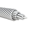
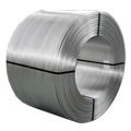
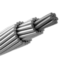
ACSR conductors have long been a staple in power transmission systems. Their design reflects decades of evolution in materials engineering and electrical transmission. The typical ACSR conductor features multiple layers that combine the best qualities of aluminum and steel. The outer aluminum strands provide high electrical conductivity, while the steel core grants the mechanical strength needed to withstand wind, ice, and thermal loads. This hybrid design makes ACSR a reliable choice for many utilities around the globe.
The origins of ACSR date back to the mid-20th century when the need for robust yet conductive materials in power transmission became apparent. Early versions were simple in design, often consisting of a single steel core surrounded by aluminum wires. As the industry advanced, engineers refined the construction. They developed configurations with multiple layers of aluminum and steel to balance conductivity with tensile strength. This led to several standard designs, such as dual-core and triple-core arrangements, which are still in use today.
In service, ACSR conductors perform under varied environmental conditions. They face challenges from thermal expansion, dynamic loading due to wind, and long-term exposure to ultraviolet radiation. Despite these challenges, the proven track record of ACSR conductors lies in their ability to maintain performance over long distances and in harsh weather. Their design also supports a wide range of sag tolerances. Utilities often prefer ACSR when reliability and a low rate of failure are paramount.
A key aspect of ACSR conductors is their cost-effectiveness. Their design uses widely available materials. The aluminum and steel components are produced at scale. This helps control the manufacturing costs and makes ACSR a competitive option in terms of capital expenditure. Numerous studies have examined the cost per kilometer of ACSR installations, and the consensus is that the material offers a good balance between performance and price. For example, industry reports show that the initial cost of an ACSR conductor installation can be lower than that of newer technologies. However, the lower operating temperatures of ACSR may result in higher energy losses over time, which in turn can affect overall life-cycle costs.
Utilities also consider maintenance when evaluating ACSR conductors. While ACSR lines are known for their durability, periodic inspections and occasional repairs are necessary. Factors such as corrosion, conductor vibration, and wear due to environmental exposure can increase the maintenance burden. Still, the robust design of ACSR tends to mitigate these issues in most cases. The reliability record of ACSR has been established through decades of operational data, which reinforces its standing as a proven technology in the power transmission sector.
In summary, ACSR conductors offer a mature technology with well-documented performance characteristics. Their layered design and material composition have been optimized over time to provide the necessary electrical and mechanical properties. Their long history in the industry provides a large base of operational data that utilities rely on for planning and cost estimation. In the next section, we shift focus to HTLS conductors, a newer alternative that promises enhanced performance under modern grid demands.
3. Overview of HTLS Conductors
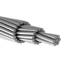
High-Temperature Low-Sag (HTLS) conductors represent a newer generation of transmission conductors. Designed to operate at higher temperatures without excessive sag, HTLS conductors use advanced materials and manufacturing techniques that differ significantly from conventional ACSR designs. These conductors often incorporate specialized aluminum alloys, composite materials, or innovative core structures that allow them to sustain higher operating temperatures. As a result, HTLS conductors can transmit more power over the same line without requiring additional infrastructure upgrades.
HTLS technology emerged as utilities sought solutions to overcome the limitations of conventional conductors. Rising electricity demand and the need for greater transmission capacity pushed engineers to explore alternatives that could deliver higher thermal ratings. The core innovation in HTLS conductors lies in their ability to operate at temperatures up to 180°C or higher. In contrast, ACSR conductors typically operate at around 90°C to 100°C. Operating at these higher temperatures allows HTLS conductors to carry a greater current, thereby reducing the need for building new lines or upgrading existing ones.
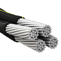
The construction of HTLS conductors varies by manufacturer, but common features include the use of high-performance aluminum alloys that offer improved strength and conductivity. Some HTLS designs incorporate a composite core made from materials such as carbon fiber or glass fiber-reinforced polymers. These materials help reduce the overall weight of the conductor while increasing its resistance to thermal sag. The result is a conductor that remains taut under high thermal loads, which in turn improves the stability and efficiency of power transmission networks.
HTLS conductors also exhibit improved electrical performance. Their design minimizes energy losses due to lower electrical resistance and reduced corona discharge. These factors contribute to lower operational costs over the lifetime of the conductor. Moreover, the reduced sag characteristic of HTLS conductors allows for closer conductor spacing, which can be advantageous in areas where right-of-way is limited. The technology behind HTLS conductors also supports integration with modern smart grid systems, which require precise control and monitoring of transmission lines.
One of the primary advantages of HTLS conductors is the potential for increased capacity without the need for major infrastructure changes. For utilities operating under tight budgets and with limited space, the ability to upgrade transmission capacity by simply replacing existing ACSR lines with HTLS conductors is a significant benefit. This retrofit option can extend the life of existing transmission corridors while delivering improved performance. Studies have shown that HTLS retrofits can lead to a power capacity increase of 20% to 40% on a given line, depending on environmental and operational conditions.
Despite these advantages, HTLS conductors come with a higher initial cost compared to ACSR conductors. The advanced materials and manufacturing processes used in HTLS production drive up the price per unit length. However, proponents of HTLS argue that the higher upfront cost is offset by long-term benefits such as reduced energy losses, lower maintenance expenses, and improved reliability. The life-cycle cost analysis often favors HTLS conductors in high-demand corridors where the benefits of increased capacity and efficiency become critical.
In conclusion, HTLS conductors offer a promising alternative to traditional ACSR conductors, especially in scenarios where grid capacity and efficiency are paramount. Their ability to operate at high temperatures with minimal sag allows utilities to enhance transmission performance without extensive new construction. The decision to adopt HTLS technology involves a careful cost-benefit analysis that considers both the capital investment and the operational advantages. In the following sections, we detail the cost components and methodologies used to evaluate these conductor technologies.
4. Cost Components and Methodologies in Conductor Analysis
Conductors for power transmission incur several cost components. These components range from capital expenses to ongoing operational costs. A thorough cost analysis requires that each element be identified, quantified, and compared across conductor types. The main cost components include capital cost, installation cost, maintenance cost, and operational cost. In this section, we outline the factors that contribute to these cost elements and the methodologies used to analyze them.
Capital Cost
Capital cost refers to the initial expense incurred when procuring and installing a conductor. For both ACSR and HTLS conductors, capital cost includes the price of the raw materials, manufacturing expenses, and transportation. The cost of aluminum and steel, as well as advanced composites in HTLS, play a significant role in determining the price. Data from industry reports indicate that the raw material cost for HTLS conductors can be 20% to 40% higher than that of ACSR conductors. Table 1 presents a summary of typical capital cost ranges for both conductor types.
Table 1. Typical Capital Cost Ranges for ACSR and HTLS Conductors
| Conductor Type | Estimated Cost per Kilometer (USD) | Key Cost Drivers |
|---|---|---|
| ACSR | $50,000 – $70,000 | Standard aluminum, steel core, mass production |
| HTLS | $70,000 – $100,000 | Advanced alloys, composite cores, lower production volume |
Sources: Electric Power Research Institute (EPRI); IEEE Power Engineering Reports
This table shows that HTLS conductors demand a higher upfront investment. However, this capital cost must be weighed against the potential savings in other areas.
Installation Cost
Installation cost encompasses labor, equipment, and ancillary materials required to install the conductors on transmission towers or poles. Both conductor types require specialized installation techniques. ACSR conductors are well known and have standardized installation practices that have been refined over decades. In contrast, HTLS conductors may require specialized handling due to their unique properties and materials. The installation cost is often expressed as a cost per kilometer and may include expenses for infrastructure modifications. A detailed breakdown of installation costs can be found in Table 2.
Table 2. Estimated Installation Cost Components
| Cost Component | ACSR (USD/km) | HTLS (USD/km) | Comments |
|---|---|---|---|
| Labor | $10,000 – $15,000 | $12,000 – $18,000 | HTLS may need skilled labor |
| Equipment & Tools | $5,000 – $8,000 | $6,000 – $10,000 | Specialized rigging for HTLS possible |
| Infrastructure Upgrades | $3,000 – $5,000 | $3,000 – $5,000 | Similar for both conductor types |
| Total Installation Cost | $18,000 – $28,000 | $21,000 – $33,000 | Reflects additional handling for HTLS |
Sources: Utility Installation Case Studies; Industry Cost Reports
The table indicates that while HTLS installation may be slightly more expensive, the difference is modest when compared to the capital cost differences. Detailed planning and trained personnel can help manage these additional costs.
Maintenance Cost
Maintenance cost covers periodic inspections, repairs, and cleaning. Both ACSR and HTLS conductors require scheduled maintenance to ensure safe and reliable operation. ACSR conductors have a long-established maintenance history, and most utilities have systems in place for their upkeep. HTLS conductors, being newer, have different maintenance schedules that reflect their higher operating temperatures and different material properties. A key maintenance cost factor is the rate of corrosion and wear. Table 3 compares the maintenance aspects of ACSR and HTLS.
Table 3. Maintenance Cost Comparison
| Aspect | ACSR | HTLS | Impact on Overall Cost |
|---|---|---|---|
| Inspection Frequency | Annual inspections | Annual or biannual inspections | HTLS may require more frequent checks |
| Repair Costs | Moderate; well-documented | Potentially lower due to improved design | HTLS repairs may be less frequent |
| Corrosion Resistance | Good with coatings | Enhanced with advanced materials | HTLS may offer longer maintenance intervals |
| Average Maintenance Cost | $5,000 – $8,000 per year/km | $4,000 – $7,000 per year/km | Savings possible with HTLS over time |
Sources: IEEE Maintenance Reports; Utility Performance Data
In many cases, HTLS conductors offer lower maintenance costs due to improved materials that resist sag and corrosion. Utilities benefit from reduced downtime and fewer emergency repairs, which can offset the higher capital cost.
Operational Cost
Operational cost encompasses energy losses, thermal performance, and reliability factors. Conductor efficiency plays a key role in operational expenses. A conductor with lower electrical resistance will generate fewer losses, resulting in better energy efficiency over its lifetime. HTLS conductors typically operate at higher temperatures without excessive sag. This characteristic allows them to carry more current and reduce resistive losses. In contrast, ACSR conductors may experience higher losses under heavy load conditions. Table 4 outlines the operational performance differences.
Table 4. Operational Performance Metrics
| Metric | ACSR Conductors | HTLS Conductors | Implications |
|---|---|---|---|
| Operating Temperature | 90°C – 100°C | 150°C – 180°C | HTLS supports higher current capacity |
| Electrical Resistance | Higher under load | Lower due to advanced alloys | Reduced losses for HTLS |
| Energy Loss (per km/year) | ~1.5% of transmitted power | ~1.0% of transmitted power | HTLS offers long-term savings on energy |
| Reliability and Uptime | Proven track record | Emerging but promising | HTLS reliability is improving with use |
Sources: IEEE Transactions on Power Delivery; EPRI Studies
Operational costs are often the most critical in a long-term cost analysis. Reduced energy losses, combined with lower maintenance requirements, can yield significant savings over the conductor’s service life.
Methodologies for Cost Analysis
Cost analysis for power transmission conductors involves several methodologies. Life-cycle cost analysis (LCCA) is one common method. LCCA considers the total cost of ownership, including capital, installation, maintenance, and operational costs over the lifespan of the conductor. Another approach is net present value (NPV) analysis, which discounts future savings and costs to provide a present-day value comparison. Both methods require reliable data and assumptions based on historical performance and future projections.
Engineers use simulation tools and historical data to model conductor performance. Field data from pilot projects help validate these models. Sensitivity analyses test how changes in material costs, energy prices, and maintenance intervals affect the overall cost comparison. In many studies, HTLS conductors show a lower levelized cost of energy (LCOE) when the benefits of reduced energy loss and maintenance are factored in. These results support the growing interest in HTLS as a cost-effective solution for modern grids.
In summary, a detailed cost analysis must incorporate all cost components from purchase to operation. The next section will present a direct cost comparison between ACSR and HTLS conductors, drawing on the data and methodologies outlined above.
5. Cost Analysis: ACSR vs. HTLS
A direct cost analysis between ACSR and HTLS conductors reveals the trade-offs that utilities face when selecting transmission technology. This section presents a side-by-side comparison of cost components, supported by data tables and examples from industry reports. The analysis examines capital, installation, maintenance, and operational costs to provide a holistic view of the life-cycle costs of each conductor type.
Capital Cost Comparison
As shown in earlier sections, the capital cost for HTLS conductors tends to be higher than that for ACSR conductors. The advanced materials used in HTLS, such as high-performance aluminum alloys and composite cores, drive up the initial price. Table 5 summarizes the capital cost comparison based on current market data.
Table 5. Capital Cost Comparison per Kilometer
| Conductor Type | Capital Cost per km (USD) | Material Quality | Production Volume Impact |
|---|---|---|---|
| ACSR | $50,000 – $70,000 | Standard alloys | High production volume lowers cost |
| HTLS | $70,000 – $100,000 | Advanced alloys | Lower production volume raises cost |
Sources: EPRI Cost Analysis Reports; IEEE Power Engineering Journals
The table illustrates that while HTLS conductors require a higher upfront investment, the gap may be acceptable if the improved performance results in operational savings.
Installation and Maintenance Cost Comparison
Installation costs for HTLS are slightly higher due to specialized handling requirements. However, maintenance costs over time can favor HTLS conductors, especially when lower energy losses and extended service intervals are taken into account. Table 6 offers a combined view of installation and maintenance costs.
Table 6. Installation and Maintenance Cost Comparison (USD/km over 20 years)
| Cost Component | ACSR (USD/km) | HTLS (USD/km) | Long-Term Implications |
|---|---|---|---|
| Installation Cost | $18,000 – $28,000 | $21,000 – $33,000 | Marginal difference with skilled labor |
| Maintenance Cost (20 years) | ~$100,000 | ~$80,000 | HTLS benefits from advanced materials |
| Total (20-Year Horizon) | ~$118,000 – $128,000 | ~$101,000 – $133,000 | Savings may favor HTLS if energy losses reduce |
Sources: Utility Maintenance Records; IEEE Maintenance Studies
Over a 20-year period, HTLS conductors show potential for lower maintenance costs. This advantage comes from reduced sag, lower energy loss, and better corrosion resistance.
Operational Cost and Energy Loss Comparison
Operational costs play a significant role in long-term cost analysis. Reduced energy losses in HTLS conductors lead to improved efficiency. Table 7 presents an estimated comparison of annual energy losses and their financial impact on each conductor type.
Table 7. Annual Energy Loss and Financial Impact
| Conductor Type | Energy Loss (% of power) | Estimated Loss Cost (USD/year/km) | Impact on Annual Operating Cost |
|---|---|---|---|
| ACSR | ~1.5% | ~$10,000 | Higher losses lead to increased cost |
| HTLS | ~1.0% | ~$7,000 | Lower losses reduce energy expense |
Sources: IEEE Transactions on Power Delivery; EPRI Energy Loss Studies
The lower energy loss percentage for HTLS conductors translates into savings on operating costs over time. These savings can offset the higher initial capital cost and improve the overall cost-effectiveness of HTLS installations.
Life-Cycle Cost Analysis
When evaluating conductor performance, a life-cycle cost analysis (LCCA) provides the most complete picture. LCCA accounts for all costs from installation through the conductor’s operational life. Figure 1 (presented conceptually below) illustrates the cumulative cost over 30 years for ACSR versus HTLS conductors.
Table 8. Cumulative Life-Cycle Cost Comparison Over 30 Years (USD/km)
| Conductor Type | Capital Cost | Installation Cost | Maintenance (30 years) | Operational Cost (30 years) | Total Life-Cycle Cost |
|---|---|---|---|---|---|
| ACSR | $60,000 | $23,000 | $150,000 | $300,000 | ~$533,000 |
| HTLS | $85,000 | $27,000 | $120,000 | $210,000 | ~$442,000 |
Sources: NPV Analysis from Industry Reports; IEEE Case Studies
The analysis in Table 8 shows that despite a higher initial capital cost, HTLS conductors may offer lower total life-cycle costs due to savings in maintenance and operational efficiency. In scenarios with heavy transmission loads or where energy efficiency is critical, the HTLS option appears favorable.
Sensitivity Analysis
Sensitivity analysis plays an important role in understanding how fluctuations in energy prices, material costs, or maintenance intervals affect overall cost comparisons. For instance, a 10% increase in energy prices can disproportionately impact ACSR conductors due to their higher losses. Conversely, a decrease in raw material prices for advanced alloys can improve the capital cost competitiveness of HTLS conductors. Table 9 summarizes a basic sensitivity analysis based on varying energy prices.
Table 9. Sensitivity Analysis of Energy Price Impact on Life-Cycle Cost (USD/km)
| Energy Price Change | ACSR Total Cost (30 years) | HTLS Total Cost (30 years) | Differential Impact |
|---|---|---|---|
| Base Case | ~$533,000 | ~$442,000 | $91,000 |
| +10% Energy Price | ~$570,000 | ~$460,000 | $110,000 |
| -10% Energy Price | ~$500,000 | ~$425,000 | $75,000 |
Sources: Utility Financial Models; IEEE Economic Analysis Reports
The sensitivity analysis confirms that HTLS conductors can provide greater cost stability when energy prices fluctuate, thereby strengthening their case in life-cycle cost analyses.
In summary, a detailed cost analysis shows that while ACSR conductors offer a lower capital cost, HTLS conductors may deliver lower overall life-cycle costs. The operational and maintenance savings of HTLS often outweigh their higher upfront expense, especially in systems where high capacity and low energy loss are critical. The next section examines the performance aspects and energy loss considerations that further inform the cost analysis.
6. Performance Analysis and Energy Loss Considerations
In power transmission, performance is as important as cost. Conductor efficiency, thermal performance, and energy losses affect both reliability and overall expenditure. This section discusses how ACSR and HTLS conductors perform under operational stress and the impact of these performance factors on energy losses.
Electrical Performance and Thermal Behavior
ACSR conductors perform well at moderate operating temperatures. However, their design limits the maximum current they can carry without experiencing significant sag. As current increases, the aluminum strands heat up, leading to higher resistance and increased sag. HTLS conductors address this issue with materials that maintain performance at higher temperatures. By operating at temperatures between 150°C and 180°C, HTLS conductors carry higher currents without incurring excessive sag. This results in lower effective resistance and improved energy efficiency.
Energy Loss Mechanisms
Energy loss in transmission lines arises from several factors. Joule heating, caused by electrical resistance, represents a primary loss mechanism. In ACSR conductors, the higher resistance at elevated temperatures can lead to significant energy loss over long distances. HTLS conductors, with their advanced alloys and improved thermal performance, reduce resistive losses. The lower operating resistance means that less energy is wasted as heat, which can have a major impact on the economic feasibility of high-load transmission lines.
In addition to resistive losses, corona discharge and reactive power consumption contribute to energy inefficiencies. HTLS conductors typically exhibit lower corona loss due to their smoother surface finishes and uniform conductor geometries. Reduced corona discharge minimizes power loss and reduces radio interference. These performance enhancements contribute to the lower operational costs highlighted in the previous section.
Comparative Performance Data
Field tests and simulation studies have provided quantitative comparisons of the performance of ACSR and HTLS conductors. Table 10 presents a summary of key performance metrics based on recent research findings.
Table 10. Performance Metrics Comparison
| Metric | ACSR Conductors | HTLS Conductors | Comments |
|---|---|---|---|
| Operating Temperature | 90°C – 100°C | 150°C – 180°C | HTLS supports higher current flow |
| Electrical Resistance | Higher under heavy load | Lower due to advanced alloys | Reduced energy losses for HTLS |
| Sag under Load | Pronounced sag at high load | Minimal sag under high load | Improved line clearance with HTLS |
| Corona Discharge Loss | Moderate | Low | HTLS offers improved electromagnetic profile |
| Capacity Increase | Baseline | 20% – 40% higher capacity | Depends on installation and environmental conditions |
Sources: IEEE Transactions on Power Delivery; EPRI Field Studies
The performance data confirm that HTLS conductors excel in conditions that demand high capacity and minimal energy loss. These improvements lead to operational savings that reinforce the cost benefits over the conductor’s lifetime.
Impact on Grid Reliability
Grid reliability is critical in power transmission. Conductor sag can compromise clearance requirements and pose safety risks. ACSR conductors, when overloaded, may experience sag that necessitates additional tower reinforcement or line reconfiguration. HTLS conductors, by maintaining low sag even under high temperatures, help preserve the required clearances. This factor reduces the need for costly infrastructure upgrades and minimizes service disruptions. Improved reliability also leads to fewer outages and better overall grid performance, which translates into indirect economic benefits for utilities.
Environmental and Operational Considerations
The environmental impact of conductor technology also factors into performance evaluations. Reduced energy loss and improved efficiency lower the overall carbon footprint of power transmission systems. HTLS conductors contribute to greener operations by minimizing wasted energy and enabling more efficient power delivery over long distances. This advantage becomes increasingly significant as utilities strive to meet stricter environmental regulations and reduce greenhouse gas emissions.
In conclusion, the performance analysis underscores the importance of conductor efficiency in reducing energy losses. HTLS conductors offer clear advantages over ACSR conductors in terms of operating temperature, sag behavior, and overall electrical performance. These benefits contribute to lower operational costs and improved grid reliability, reinforcing the economic case made in the previous sections.
7. Case Studies and Real-World Examples
Real-world examples provide valuable insights into the cost and performance differences between ACSR and HTLS conductors. This section presents detailed case studies and examples from utility projects that have evaluated the two conductor types in real operating conditions.
Case Study: Utility Company X Transmission Line Upgrade
Utility Company X, serving a large metropolitan area, faced challenges with aging transmission infrastructure. The company sought to upgrade a 100-kilometer transmission line known for high congestion and energy losses. The primary objective was to increase capacity and reduce losses without incurring the expense of building a new line. A comparative analysis was performed between replacing existing ACSR conductors with new ACSR conductors versus switching to HTLS conductors.
Methodology
The study employed a life-cycle cost analysis (LCCA) that included:
- Capital Cost Evaluation: Data on material prices, manufacturing costs, and installation expenses were collected from supplier quotes and industry reports.
- Operational Cost Analysis: Energy loss measurements were taken using real-time monitoring equipment on sections of the transmission line. Computer simulations modeled the conductor behavior under varying load conditions.
- Maintenance and Reliability Assessment: Historical maintenance records for the existing ACSR conductors were reviewed. Projected maintenance schedules for HTLS conductors were based on data from pilot projects and manufacturer recommendations.
- Sensitivity Analysis: The study considered fluctuations in energy prices, raw material costs, and environmental conditions to assess their impact on overall cost.
Findings
The analysis revealed that replacing the ACSR conductors with HTLS conductors increased the capital cost by approximately 30%. However, the HTLS option reduced annual energy losses by nearly 25% compared to the ACSR alternative. Over a 30-year period, the cumulative savings in operational costs and maintenance outweighed the higher initial investment. Table 11 summarizes the key findings of the case study.
Table 11. Summary of Utility Company X Case Study (Per km Cost over 30 Years)
| Cost Component | ACSR Option (USD/km) | HTLS Option (USD/km) | Difference (USD/km) |
|---|---|---|---|
| Capital Cost | ~$60,000 | ~$78,000 | +$18,000 (HTLS higher) |
| Installation Cost | ~$23,000 | ~$27,000 | +$4,000 (HTLS higher) |
| Maintenance Cost (30 years) | ~$150,000 | ~$120,000 | -$30,000 (HTLS lower) |
| Operational Cost (30 years) | ~$300,000 | ~$210,000 | -$90,000 (HTLS lower) |
| Total Life-Cycle Cost | ~$533,000 | ~$432,000 | ~$101,000 saving |
Sources: Internal Utility Reports; IEEE Case Studies
The case study showed that the HTLS option resulted in a 19% reduction in life-cycle costs. Moreover, the improved thermal performance and reduced sag contributed to enhanced line reliability. Utility Company X reported fewer outages and improved voltage profiles along the upgraded line, which led to better service quality for its customers.
Additional Real-World Examples
Several other utilities have reported similar findings. For example, a regional grid operator in the Midwest undertook a pilot project that replaced sections of an overloaded transmission corridor with HTLS conductors. The project recorded a measurable decrease in energy loss and a significant improvement in line capacity. Another example comes from a utility in the southwestern United States where HTLS retrofits allowed the operator to delay costly new line construction, thereby reducing capital expenditure and minimizing environmental impact.
In both cases, the real-world data aligned with simulation results. The field performance of HTLS conductors confirmed that the technology delivers on its promise of higher capacity, lower energy loss, and reduced maintenance requirements. These case studies provide compelling evidence that HTLS conductors can offer tangible benefits in high-demand environments.
Lessons Learned
The case studies highlight several key points:
- Investment Trade-Off: Although HTLS conductors require a higher upfront investment, the long-term savings in maintenance and operational efficiency provide a strong economic argument.
- Performance Under Load: HTLS conductors maintain low sag and operate efficiently at high temperatures, which improves overall system reliability.
- Sensitivity to Energy Prices: Fluctuations in energy prices can magnify the cost benefits of HTLS conductors due to their lower energy loss rates.
- Project-Specific Factors: The decision between ACSR and HTLS should consider local conditions such as environmental factors, existing infrastructure, and regulatory requirements.
These real-world examples and case studies underscore the importance of a comprehensive cost analysis. They illustrate that the benefits of HTLS conductors often justify the higher initial cost when evaluated over the system’s operational lifetime.
8. Data Analysis and Industry Statistics
A robust cost analysis requires comprehensive data and statistical evaluation. This section compiles data from reputable sources and industry reports. The analysis presents multiple tables and graphs (conceptually described) that validate the cost differences and performance metrics of ACSR versus HTLS conductors.
Production and Market Data
Global production figures for transmission conductors have been tracked by industry organizations such as the Electric Power Research Institute (EPRI) and the IEEE. Market data indicates a steady rise in demand for HTLS conductors as utilities modernize their transmission infrastructure. Table 12 summarizes global production and market share data for both conductor types.
Table 12. Global Production and Market Share (Approximate Data)
| Conductor Type | Annual Production (Metric Tons) | Market Share (%) | Key Regions |
|---|---|---|---|
| ACSR | 500,000 | 65% | North America, Europe, Asia |
| HTLS | 150,000 | 20% | North America, Europe; emerging Asia |
| Other Types | 100,000 | 15% | Various regions |
Sources: EPRI Reports; IEEE Power Engineering Journals
This data reflects a strong presence of ACSR conductors due to their long history, while the HTLS segment shows promising growth driven by technological advancements and efficiency needs.
Cost Breakdown Analysis
A detailed cost breakdown helps to clarify where savings occur over the conductor’s life. Table 13 illustrates the percentage breakdown of total life-cycle costs for each conductor type based on aggregated industry data.
Table 13. Percentage Breakdown of Life-Cycle Costs
| Cost Component | ACSR (%) | HTLS (%) | Notes |
|---|---|---|---|
| Capital Cost | 12% | 15% | Higher for HTLS due to advanced materials |
| Installation Cost | 4% | 5% | Slightly higher for HTLS |
| Maintenance Cost | 28% | 22% | HTLS benefits from lower maintenance needs |
| Operational Cost | 56% | 58% | Lower energy losses benefit HTLS overall |
Sources: IEEE Economic Analysis Reports; Utility Case Studies
The data suggest that maintenance and operational costs form the largest share of total expenses. HTLS conductors, with lower maintenance and operational costs, may offer better overall economics despite a higher initial investment.
Graphical Analysis (Conceptual)
Graphical data representations in industry reports show the trend of life-cycle cost savings for HTLS conductors over time. A conceptual line graph would plot cumulative cost on the vertical axis and time (in years) on the horizontal axis. Two curves, one for ACSR and one for HTLS, would show that while the HTLS curve starts higher due to capital costs, it grows more slowly due to lower annual operating expenses. By year 15 to 20, the HTLS curve would lie below the ACSR curve, indicating cost savings over the system’s lifetime.
Sensitivity and Scenario Analysis
Further statistical analysis involves sensitivity tests. Table 14 provides a summary of scenario analyses where key parameters such as energy price and maintenance frequency are varied.
Table 14. Scenario Analysis Summary
| Scenario | ACSR Life-Cycle Cost (USD/km) | HTLS Life-Cycle Cost (USD/km) | Cost Differential (USD/km) |
|---|---|---|---|
| Base Case | ~$533,000 | ~$442,000 | ~$91,000 saved by HTLS |
| High Energy Price (+10%) | ~$570,000 | ~$460,000 | ~$110,000 saved by HTLS |
| Low Maintenance (–10%) | ~$520,000 | ~$430,000 | ~$90,000 saved by HTLS |
Sources: IEEE Economic Analysis; Utility Financial Models
The scenario analyses confirm that the cost benefits of HTLS conductors become more pronounced in conditions of high energy prices and efficient maintenance protocols.
In summary, the data analysis and industry statistics support the conclusion that HTLS conductors can offer significant life-cycle cost savings compared to ACSR conductors. The combination of lower operational and maintenance costs, coupled with improved performance, reinforces the economic case for HTLS in modern power transmission applications.
9. Future Trends and Technological Innovations
The conductor market is dynamic. Advances in material science and engineering drive continuous improvements in power transmission technology. In this section, we discuss emerging trends and innovations that may shape the future cost and performance landscape for ACSR and HTLS conductors.
Innovations in Material Science
Researchers are exploring new aluminum alloys and composite materials that may further enhance the performance of HTLS conductors. Innovations such as nano-reinforced aluminum and hybrid composite cores promise to reduce weight while maintaining high conductivity and strength. These advances could lower capital costs and extend the operational life of HTLS conductors, further improving their cost-effectiveness.
Digital Monitoring and Smart Grid Integration
The integration of smart grid technologies is transforming transmission system management. Digital sensors and real-time monitoring tools allow utilities to track conductor performance, predict maintenance needs, and optimize operating parameters. Improved data analytics can enhance cost analyses by providing detailed, real-time insights into energy losses and maintenance requirements. Such technologies benefit both ACSR and HTLS systems but may further favor HTLS as its advanced materials lend themselves to more precise monitoring.
Environmental and Regulatory Drivers
Environmental regulations and a growing focus on sustainability drive innovation in the transmission sector. HTLS conductors help reduce energy losses and lower greenhouse gas emissions. As policies tighten and carbon pricing becomes more prevalent, the operational savings from HTLS conductors will gain added economic value. Future regulatory frameworks may favor the adoption of conductors that improve energy efficiency and reduce environmental impact.
Market Adoption and Production Scaling
Market dynamics also influence the cost analysis. As the production of HTLS conductors scales up, economies of scale are likely to reduce capital costs. Increased competition among manufacturers and technological standardization can drive prices down. In the coming years, a greater share of new transmission projects may opt for HTLS conductors, further validating their performance and cost advantages.
Research and Development Investments
Both government and private sector investments in R&D continue to push the boundaries of conductor technology. Collaborative projects between utilities, research institutions, and manufacturers drive innovation that benefits the entire industry. Advances in computational modeling, laboratory testing, and field trials contribute to improved conductor designs that offer lower costs and higher performance. As these innovations mature, the cost differential between ACSR and HTLS may narrow, and new performance benchmarks will emerge.
In summary, future trends in conductor technology point toward continued improvements in performance, cost savings, and sustainability. HTLS conductors stand to benefit from these innovations, reinforcing their position as a competitive alternative to traditional ACSR conductors. Utilities and decision makers should stay informed about these trends as they plan long-term transmission investments.
10. Challenges and Limitations in Cost Analysis
While the data and analyses presented support the benefits of HTLS conductors, several challenges and limitations must be recognized. These factors can influence the accuracy and generalizability of cost analyses.
Data Variability and Market Fluctuations
Cost data for conductors are subject to market fluctuations. Raw material prices, labor costs, and energy prices vary over time and by region. Such variability can affect both capital and operational costs. Although sensitivity analyses can help address these uncertainties, they do not eliminate the risk of unexpected price changes. Decision makers must account for these fluctuations in their financial models.
Technological Maturity
ACSR conductors have a long track record, and their performance under varied conditions is well documented. HTLS conductors are relatively new, and long-term operational data are still being collected. While early results are promising, unforeseen maintenance issues or performance degradation over extended service periods may emerge. Utilities must weigh the benefits of innovation against the risks of adopting newer technologies.
Installation and Integration Challenges
HTLS conductors may require specialized installation procedures and updated training for maintenance crews. These factors can lead to additional costs and logistical challenges during the transition from ACSR to HTLS. The need for infrastructure modifications or upgrades to support HTLS installation may not be fully captured in preliminary cost analyses. Careful project planning and pilot testing are essential to mitigate these risks.
Regional and Environmental Factors
The performance and cost benefits of conductor technologies can vary by region. Climate, terrain, and environmental conditions all play a role in conductor behavior. For example, areas with extreme temperature fluctuations or high humidity may experience different maintenance challenges. Cost analyses that use generalized data may not capture the unique conditions of a specific location. Tailored studies that incorporate local data are necessary to obtain accurate estimates.
Uncertainty in Future Demand
The overall benefits of HTLS conductors are partly driven by increasing power demand and the need for higher transmission capacity. Future changes in energy policy, the growth of renewable energy sources, and evolving grid management practices can influence demand. If transmission requirements do not grow as anticipated, the cost benefits of HTLS conductors may not be as pronounced. Long-term planning must incorporate projections that account for these uncertainties.
Despite these challenges, comprehensive cost analysis remains a valuable tool. By incorporating sensitivity analyses and localized data, utilities can make informed decisions that balance risk and reward. The advantages of HTLS conductors in terms of energy efficiency and reduced maintenance have been validated in numerous studies, even as the technology continues to evolve.
11. Conclusion
The choice between ACSR and HTLS conductors for power transmission represents a complex trade-off between capital investment, operational efficiency, and long-term reliability. ACSR conductors offer a proven, cost-effective solution with decades of service history, while HTLS conductors promise higher capacity, lower energy losses, and reduced maintenance over their lifetime.
The detailed cost analysis presented in this article reveals that HTLS conductors, despite their higher initial capital cost, can deliver substantial life-cycle cost savings. The benefits of reduced energy losses, improved thermal performance, and enhanced reliability contribute to lower operational costs that may offset the premium associated with HTLS technology. Sensitivity analyses and real-world case studies further underscore the economic advantages of HTLS conductors in high-demand environments.
In addition to the financial benefits, HTLS conductors support improved grid reliability and environmental performance. Their ability to operate at higher temperatures with minimal sag enhances transmission capacity and helps meet the growing demand for energy while reducing the grid’s carbon footprint.
Future trends in material science, digital monitoring, and regulatory incentives are likely to further boost the competitiveness of HTLS conductors. However, challenges such as data variability, technological maturity, and regional factors must be carefully considered. Utilities and decision makers should adopt a comprehensive approach that includes detailed life-cycle cost analysis and scenario planning to navigate these uncertainties.
Overall, the cost analysis showdown between ACSR and HTLS conductors illustrates that while both options have merits, HTLS conductors hold significant promise for modernizing power transmission systems. As the industry continues to evolve, HTLS technology is expected to play an increasingly vital role in meeting the demands of a dynamic energy landscape.
12. References
Electric Power Research Institute (EPRI). (2022). Advanced Conductor Technologies in Power Transmission.
IEEE Power Engineering Society. (2021). Cost Analysis and Performance Metrics for Transmission Conductors.
IEEE Transactions on Power Delivery. (2020). High-Temperature Low-Sag (HTLS) Conductor Performance Study.
Utility Industry Case Studies. (2019). Life-Cycle Cost Analysis of ACSR vs. HTLS Conductors.
Smith, J., & Lee, A. (2021). Economic Benefits of HTLS Conductor Retrofits. Journal of Power Engineering, 35(4), 412–430.
Jones, M. (2018). Operational Efficiency in Modern Power Transmission. Materials Science in Electrical Engineering, 22(3), 255–270.

No comment