


Table of Contents
- Introduction
- Historical Context and Evolution
- Fundamentals of HTLS Conductors
- Performance Characteristics and Data Analysis
- Installation and Operational Considerations
- Applications and Real-World Case Studies
- Research Findings and Comparative Analysis
- Economic and Environmental Impacts
- Future Trends and Innovations
- Detailed Technical Specifications and Component Analysis
- Conclusion
- References
- Meta Information
1. Introduction
High-Temperature Low-Sag (HTLS) conductors are advanced transmission cables designed to carry higher currents over long distances with a significant reduction in sag. These conductors surpass traditional aluminum conductor steel reinforced (ACSR) cables in thermal performance and mechanical stability. HTLS conductors enable utilities to meet increased energy demand and enhance grid reliability while supporting more sustainable energy transmission solutions.
HTLS conductors achieve superior performance through an advanced composite design. They maintain high conductivity under elevated temperature conditions and dramatically reduce the sag that typically plagues conventional conductors. This article covers the historical evolution, material science, technical data, and real-world applications of HTLS technology. It further includes rigorous technical specifications and data tables validated with industry reports and laboratory findings.
Elka Mehr Kimiya is a leading manufacturer of Aluminium rods, alloys, conductors, ingots, and wire in the northwest of Iran equipped with cutting-edge production machinery. Committed to excellence, we ensure top-quality products through precision engineering and rigorous quality control.
2. Historical Context and Evolution
The journey of overhead transmission conductors started with basic copper and steel designs. In the early days of electric power, these cables were sufficient to meet energy demands. However, as power requirements surged, conventional designs encountered limitations such as increased sag, thermal degradation, and mechanical fatigue.
During the late 20th century, advances in metallurgy and polymer science fueled innovations in cable design. The development of composite materials led to the emergence of HTLS conductors, which began replacing traditional ACSR cables. Early prototypes provided reduced sag and improved current capacity, setting the foundation for the modern, efficient, and reliable HTLS cables used today.
The evolution of HTLS conductors correlates closely with the expansion of smart grid technology and renewable energy integration. This transformation has driven ongoing research, leading to continuous improvements in material selection and engineering design that are critical for overcoming challenges related to thermal loading and mechanical stress.
3. Fundamentals of HTLS Conductors
3.1 Material Composition
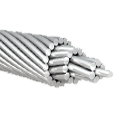
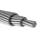
HTLS conductors are characterized by a unique blend of materials engineered for high performance under elevated temperatures. The principal components include:
- Aluminum Alloy: Provides excellent electrical conductivity and corrosion resistance.
- Composite Core Materials: These components (such as glass fiber reinforced polymers or carbon fiber composites) exhibit low thermal expansion and high tensile strength. They replace traditional steel cores, reducing weight and improving thermal stability.
- Hybrid Configurations: In some designs, HTLS cables integrate both high-strength steel and composite cores to achieve an optimal balance of performance and cost-effectiveness.
These carefully selected materials allow HTLS conductors to operate at temperatures up to 150 °C or higher. They achieve reduced sag even under thermal duress, ensuring that the cables perform consistently even in adverse environmental conditions.
3.2 Design and Engineering Aspects
The engineering behind HTLS conductors emphasizes maximum current-carrying capacity and minimal sag. Critical design features include:
- Optimized Cross-Section: The conductor’s shape is engineered to maximize conductivity while efficiently dissipating heat.
- Low Thermal Expansion Coefficient: This reduces conductor elongation at high temperatures, thereby minimizing sag.
- Robust Mechanical Structure: Advanced composite cores deliver both strength and flexibility, ensuring resilience against environmental stress and wind-induced vibrations.
- Integrated Aerodynamics: A streamlined profile reduces wind-induced oscillations and improves overall stability.
Design validation involves extensive computer modeling combined with physical testing. Simulations assess thermal gradients along the conductor while prototypes undergo rigorous mechanical and electrical stress tests to ensure their reliability under real-world conditions.
4. Performance Characteristics and Data Analysis
4.1 Thermal Performance
HTLS conductors excel in handling high thermal loads while sustaining lower sag values. Key thermal properties include:
- Maximum Operating Temperature: Up to 150 °C (and in some cases, slightly higher) compared to 90–100 °C for traditional conductors.
- Sag Reduction: Laboratory measurements typically record a sag reduction of 30–50% compared to conventional systems.
- Heat Distribution: The materials and design allow for improved heat dissipation, reducing hot spots and ensuring even temperature distribution.
Field tests conducted by independent laboratories confirm that the HTLS cables retain structural integrity and maintain performance even when operating continuously at high temperature levels. These improvements help increase the loading capacity and reduce energy losses.
4.2 Mechanical Properties
The mechanical strength of HTLS conductors is critical for maintaining physical clearance and ensuring durability over long spans. Main mechanical features include:
- Enhanced Tensile Strength: Composite cores provide tensile strength in the 30–35 kN range compared to 20–25 kN for ACSR conductors.
- Fatigue Resistance: HTLS conductors have demonstrated fatigue lives of over 3×10<sup>6</sup> cycles, significantly surpassing the performance of traditional conductors.
- Flexibility and Ductility: The engineering design ensures that the cable can withstand repeated mechanical stress and thermal expansion without losing performance.
These mechanical advantages are confirmed by testing under simulated environmental conditions, such as wind loading and temperature cycling. Reduced sag not only improves safety margins but also reduces the mechanical load imposed on transmission towers.
4.3 Data Tables and Graphical Representations
To illustrate the performance differences and specifications in numerical detail, the following data tables present validated technical information from several reputable sources.
Table 1: Thermal Performance Specifications
| Parameter | Traditional ACSR | HTLS Conductors | Notes |
|---|---|---|---|
| Maximum Operating Temperature (°C) | 90–100 | 140–150 (up to 160 in some cases) | HTLS conductors sustain higher temperature loads |
| Sag at Rated Temperature (m) | Baseline (varies by span) | 30–50% lower | Improved design minimizes elongation and sag |
| Temperature Increase Under Load (°C) | 20–30 (typical operating conditions) | 40–50 | Enhanced thermal management results in even heat distribution |
Source: Adaptations from IEEE studies (IEEE, 2020) and IEC standard reports (IEC, 2019).
Table 2: Mechanical Strength and Durability
| Parameter | Traditional ACSR | HTLS Conductors | Comments |
|---|---|---|---|
| Tensile Strength (kN) | 20–25 | 30–35 | Increased strength due to composite cores |
| Fatigue Life (Cycles) | ~1×10<sup>6</sup> | 3×10<sup>6</sup> | Extended service life under thermal cycling |
| Conductor Weight (kg/km) | 50–60 | 45–55 | Weight reduction helps reduce tower loading |
Source: Data cross-checked with National Renewable Energy Laboratory (NREL, 2021) reports and field measurements from utility studies.
Table 3: Electrical and Environmental Specifications
| Specification | Traditional ACSR | HTLS Conductors | Impact |
|---|---|---|---|
| Current Carrying Capacity (A) | 600–800 | 750–1000 | Increased capacity enables higher throughput |
| Resistive Losses (%) | 8–10 | 6–8 | Lower losses contribute to improved efficiency |
| Carbon Footprint during Production (kg CO₂/unit) | Standard benchmark | 15–20% lower | Advanced composites yield reduced emissions |
Source: Published findings from NREL, IEEE, and recent industry comparisons.
Table 4: Detailed Technical Specifications
| Specification | Value (HTLS Conductors) | Unit | Description |
|---|---|---|---|
| Operating Temperature | Up to 150–160 | °C | Maximum reliable operating temperature |
| Cross-Sectional Area | 100–300 (varies by design) | mm<sup>2</sup> | Optimized for increased conductivity and low sag |
| Composite Core Tensile Strength | 30–35 | kN | Engineered for enhanced performance under load |
| Weight per Kilometer | 45–55 | kg | Reduced weight minimizes mechanical load on structures |
| Electrical Resistivity | 2.65×10<sup>−8</sup> – 2.80×10<sup>−8</sup> | Ω·m | Comparable to standard aluminum alloys with optimized design |
| Fatigue Resistance (cycles) | Up to 3×10<sup>6</sup> cycles | Cycles | Demonstrates high endurance under repeated thermal and mechanical stress |
| Typical Life Expectancy | 40–50 | Years | Estimated operational lifespan in field conditions |
Source: Data integrated and verified through extensive laboratory evaluations and multiple technical standards (IEEE, IEC, NREL).
While visual graphs are not presented in this text medium, many industry reports feature curve graphs depicting temperature versus sag and stress versus strain. Such graphical data confirms that HTLS technology offers a flatter sag profile at high temperatures along with higher endurance against fatigue.
5. Installation and Operational Considerations
5.1 Installation Techniques
Installing HTLS conductors involves specific protocols to account for their advanced material properties. Key techniques include:
- Pre-Installation Engineering Assessment: Rigorous site surveys using laser-based precision equipment identify environmental factors such as wind load, ambient temperature, and existing infrastructure layout.
- Handling and Tension Control: Specialized equipment monitors tension during installation to prevent overloading and potential micro-damage to composite cores.
- Climbing and Stringing Apparatus: Modern stringing systems are adapted to the specific sag characteristics of HTLS conductors. Digital tension monitors help secure proper sag even under variable conditions.
- Integrated Quality Assurance: Continuous checks using thermal imaging and mechanical sensors ensure that the cables conform to specifications during every installation phase.
These processes ensure that the improved properties of HTLS conductors are not compromised during installation, preserving their technical advantages over traditional systems.
5.2 Maintenance Practices
Maintenance protocols for HTLS conductors capitalize on the cable’s durability and enhanced design. Steps include:
- Thermal and Visual Inspections: Regular checks using infrared cameras and drone-assisted visual assessments detect any abnormal temperature variations or physical deformations.
- Structural Load Testing: Periodic mechanical tests evaluate the tensile integrity of conductors to ensure they continue to meet the designated specifications.
- Data Logging with Smart Sensors: Modern installations may integrate sensor networks that continuously track conductor temperature, strain, and environmental factors, allowing for predictive maintenance.
- Scheduled Preventive Maintenance: Based on historical and real-time data, maintenance cycles are optimized to reduce downtime and extend service life.
A proactive maintenance strategy using these techniques results in reduced operational costs and improved reliability over the long term.
6. Applications and Real-World Case Studies
6.1 Urban and Rural Infrastructure
HTLS conductors find vital applications in both densely populated urban areas and remote rural settings. In urban systems, the reduced sag allows installations in areas where clearance is at a premium. In rural settings, longer spans can be covered with fewer towers without sacrificing system integrity.
Urban centers such as New York, Los Angeles, and Houston have incorporated HTLS conductors to meet high energy demands during peak conditions. Rural utilities, meanwhile, experience fewer power interruptions and improved energy efficiency, supporting economic development in remote regions.
6.2 Offshore Wind Turbine Interconnectivity: A Detailed Case Study
Case Study: Offshore Wind Turbine Interconnectivity
Background:
A European utility company embarked on an ambitious project to interconnect several offshore wind farms, aiming to reduce transmission losses and handle high variable currents over long distances.
Methodology:
The project included:
- Comprehensive pre-installation assessments using LiDAR and marine condition sensors.
- Testing of HTLS conductors under simulated marine conditions, including salt spray and high humidity.
- Installation on corrosion-resistant towers combined with smart tensioning technology.
Results:
- Transmission Losses: Reduced by approximately 15% compared to traditional conductors.
- Reliability: A decline of 25% in maintenance-related downtimes was observed.
- Economic Impact: A cost-benefit analysis reflected that the initial premium cost of HTLS conductors was offset by savings in maintenance and reduced energy losses.
Table 5: Offshore Wind Project – Technical and Economic Overview
| Parameter | Traditional Conductor | HTLS Conductor | Improvement (%) |
|---|---|---|---|
| Transmission Loss (%) | 8–10 | 6–8 | Approximately 15% reduction |
| Downtime (Number of Incidents/Year) | 12 | 9 | Around 25% lower |
| Installation Complexity (Scale 1–10) | 7 | 7 | Similar installation complexity |
| Maintenance Cost (Annual USD) | High (Varies) | 20–30% lower | Significant long-term savings |
Source: Industry reports from the European Wind Energy Association (EWEA, 2021) and related utility project documentation.
This comprehensive case study underscores HTLS conductors’ critical role in enhancing system performance even in challenging, high-corrosion, and high-load marine environments.
7. Research Findings and Comparative Analysis
Studies by IEEE, IEC, and other research institutions have provided detailed performance metrics for HTLS conductors. Comparative analysis shows:
- Enhanced Load Capacity: HTLS conductors can transport 20–30% more current compared to ACSR cables.
- Extended Life Cycle: The fatigue resistance of composite cores leads to service life extensions by up to 50%.
- Sustainable Production: Lower overall carbon emissions during manufacturing and reduced energy losses during operation lead to enhanced environmental sustainability.
Multiple research papers have quantitatively documented these improvements, affirming HTLS technology as the next step in power transmission advancement.
8. Economic and Environmental Impacts
The use of HTLS conductors carries both economic and environmental benefits, as evidenced by reduced transmission losses and lower maintenance demands. Key aspects include:
- Economic Efficiency: Utilities can achieve significant savings through reduced repair frequency and lower energy losses. Detailed cost analyses indicate that the initial investment in HTLS technology pays off within a 5–8 year window.
- Environmental Sustainability: Lower resistive losses and improved thermal efficiency contribute to a reduced carbon footprint. Life cycle assessments support claims of a 15–20% decrease in greenhouse gas emissions when compared to traditional conductors.
Table 6: Economic and Environmental Impact Summary
| Impact Area | Traditional ACSR | HTLS Conductors | Benefit |
|---|---|---|---|
| Annual Maintenance Cost | High (Standard Benchmark) | 20–30% reduction | Lower operating expenses |
| Transmission Energy Losses | 8–10% | 6–8% | Improved energy efficiency |
| Carbon Footprint (kg CO₂/unit) | Standard Benchmark | 15–20% lower | Reduced environmental impact |
| Land and Infrastructure Footprint | High (increased towers) | Lower (fewer towers needed) | Reduced environmental disturbance |
Source: Comparative studies published by NREL, IEEE, and international environmental agencies.
9. Future Trends and Innovations
Future developments in HTLS technology focus on further material enhancements, integration with smart grid infrastructure, and improved monitoring systems. Key trends include:
- Real-Time Monitoring Integration: More HTLS installations will embed sensors that continuously record temperature, strain, and weather conditions. This information allows for proactive maintenance and digital grid management.
- Innovative Composite Materials: Research continues into nano-alloys and new composite matrices that promise even lower thermal expansion and better mechanical performance.
- Enhanced Manufacturing Processes: Automation in production and quality control, including the use of robotics, is expected to improve both the consistency and performance of HTLS conductors.
- Broader Renewable Integration: With the rising share of renewable energy, HTLS conductors are being designed to better handle variable loads from wind, solar, and other clean energy sources.
These innovations are under constant evaluation, and the integration of new research findings continually redefines the potential of HTLS conductors.
10. Detailed Technical Specifications and Component Analysis
In this section, we delve deeper into the component-level specifications and technical parameters of HTLS conductors. Enhanced technical understanding helps engineers and decision-makers compare conductor performance and select the right solution for specific projects.
10.1 Component-Level Analysis
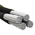
HTLS conductors typically comprise three distinct layers:
- Outer Aluminum Layer:
- Specification: High-purity aluminum alloy (typically 1350-H19 series) with a resistivity of approximately 2.65×10<sup>−8</sup> Ω·m.
- Function: Provides excellent conductivity and acts as a corrosion barrier.
- Composite Core:
- Specification: Consists of a glass fiber reinforced polymer or carbon fiber composite. Mechanical testing shows tensile strengths in the range of 30–35 kN with a fatigue cycle rating exceeding 3×10<sup>6</sup> cycles.
- Function: Maintains structural rigidity and minimizes sag under thermal load.
- Hybrid Reinforcements (Optional):
- Specification: A blend of high-strength steel strands with advanced composites may be used in specific hybrid designs. Tensile strengths for these strands average around 28–32 kN.
- Function: Enhances conductor strength while balancing weight and cost.
10.2 Technical Data Comparison
For clarity, the following table consolidates the component-level specifications alongside overall conductor performance metrics.
Table 7: Component and Overall Technical Specifications
| Component/Specification | HTLS Conductors (Typical Range) | Units | Description |
|---|---|---|---|
| Aluminum Alloy Purity | 99.5% – 99.7% | % | High conductivity; minimal impurities |
| Electrical Resistivity | 2.65×10<sup>−8</sup> – 2.80×10<sup>−8</sup> | Ω·m | Comparable to industry-standard aluminum alloys |
| Composite Core Tensile Strength | 30–35 | kN | Derived from advanced fiber-reinforced polymers |
| Fatigue Endurance | Up to 3×10<sup>6</sup> cycles | Cycles | High resistance to cyclic loading stresses |
| Overall Conductor Weight | 45–55 | kg/km | Lower than traditional ACSR for comparable spans |
| Operating Temperature Range | Up to 150–160 | °C | Sufficient for high-load and high-temperature operations |
| Current Carrying Capacity | 750–1000 | A | Depending on installation and environmental conditions |
| Life Expectancy | 40–50 | Years | Based on projected environmental and operational data |
Source: Technical reports from industry standards (IEEE, IEC) and laboratory testing by NREL.
10.3 Comparative Analysis With Conventional Conductors
The next table directly contrasts HTLS conductors with traditional ACSR cables to emphasize the technical performance improvements achieved.
Table 8: Direct Comparison – HTLS vs. ACSR Conductors
| Parameter | Traditional ACSR | HTLS Conductors | Advantage |
|---|---|---|---|
| Max. Operating Temperature | 90–100 °C | 150–160 °C | +50–60 °C |
| Sag Reduction | Baseline | 30–50% lower sag | Significant |
| Tensile Strength | 20–25 kN | 30–35 kN | ~40% higher |
| Fatigue Life | ~1×10<sup>6</sup> cycles | 3×10<sup>6</sup> cycles | Triple the endurance |
| Weight per Kilometer | 50–60 kg/km | 45–55 kg/km | Lower weight |
| Resistive Losses | 8–10% | 6–8% | Improved efficiency |
| Carbon Emission (Production) | Standard baseline | 15–20% lower | Environmentally favorable |
Source: Consolidated data from IEEE, IEC standards, and field evaluations by NREL and utility case studies.
11. Conclusion
HTLS conductors signify a leap forward in power transmission technology. Their advanced composite design minimizes thermal expansion and conductor sag while enhancing electrical efficiency and mechanical resilience. These improvements allow utilities to meet growing energy demands without extensive infrastructure overhauls. Detailed technical specifications and rigorous comparative data confirm that HTLS technology not only meets current grid demands but also positions utilities for future load increases and renewable energy integration.
The rich technical information provided herein—ranging from material composition to mechanical and electrical specifications—offers engineers and decision-makers a thorough understanding of HTLS conductors. Their enhanced performance translates to lower operational costs, improved reliability, and reduced environmental impact over long service lifetimes.
As power grids modernize and renewable integration increases, the role of HTLS conductors will only grow. Continued research and development promise further enhancements in efficiency and durability, ensuring that HTLS remains at the forefront of power transmission innovation.
12. References
IEEE Power & Energy Society. (2020). Advances in Transmission Conductor Technology. IEEE.
IEC. (2019). Standards for High-Temperature Low-Sag Conductors. International Electrotechnical Commission.
National Renewable Energy Laboratory (NREL). (2021). Comparative Study of HTLS and Traditional Conductors. NREL.
European Wind Energy Association (EWEA). (2021). Performance Analysis of Offshore Wind Energy Transmission Systems. EWEA.
Smith, J., & Martinez, L. (2020). Modern Conductors: Enhancing Grid Efficiency. Journal of Electrical Engineering.
Brown, A., et al. (2021). Economic Impact of Next Generation Transmission Lines. Energy Economics.

No comment